Circuit simulations are often performed with ideal conditions; however, circuits rarely operate this way in the field due to external factors such as noise and temperature variations. These external influences can negatively affect circuit behavior, for example, resistance naturally increases at higher temperatures and capacitance can be affected as well depending on the type of capacitor. In such situations, ideal simulation results may no longer apply. Quickly and easily perform a temperature sweep in PSpice Designer to analyze real-world results and ensure your circuit functions as intended across its operating temperature range.
This quick how-to will provide step-by-step instructions on how to perform a temperature sweep in PSpice Designer.
To follow along, download the provided files above the table of contents.
How-To Video
 Open in New Window
Placing Thermally Sensitive Components
Step 1: Open the provided design in PSpice Designer.
Step 2: To place a transistor with a temperature-sensitive model in the design, select Place > Component from the menu.
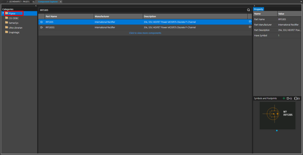
Step 3: The Component Explorer tab opens. From here, you can place symbols with SPICE models assigned as well as pre-mapped symbols from SamacSys, Ultra Librarian, and more.
Ensure the PSpice category is selected.
Step 4: Enter IRF5305 into the Search field and press Enter.
Step 5: Two MOSFETs are listed. Select the MOSFET labeled IRF5305 to view its properties under Symbols and Footprints on the right side of the screen.
Note: A preview of the symbol is shown in the panel. This symbol is meant for simulation and has no PCB footprint associated with it.
Step 6: Right-click the MOSFET and select Place to place it in the schematic.
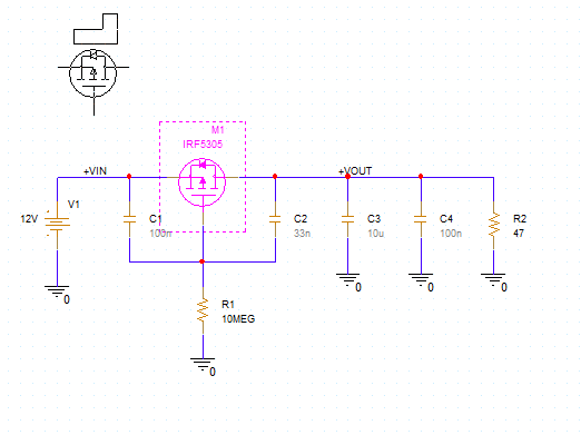
Step 7: Click to place the MOSFET as shown in the empty space in the schematic. Use the R and H keys on the keyboard to rotate and flip as required. Right-click and select End Mode.
Perform a Temperature Sweep: Simulation Setup
Step 8: To create a simulation profile, select PSpice > New Simulation Profile from the menu.
Step 9: The New Simulation window opens. Enter a name for the simulation and click Create.
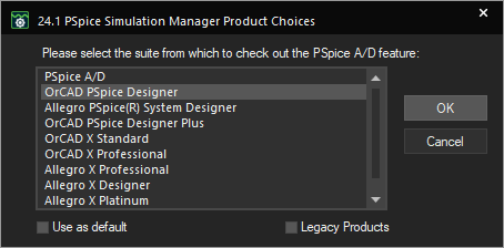
Note: If the Simulation Manager Product Choices window opens, select the appropriate license and click OK.
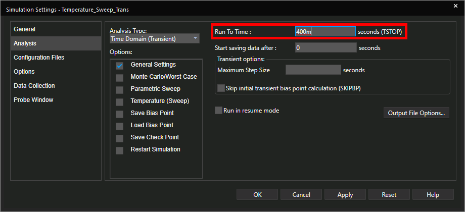
Step 10: The Simulation Settings window opens to the General Settings subpanel. Here you can configure simulation settings such as the type of simulation, the resolution, and additional options such as sweeps. Enter 400m for the Run To Time.
Step 11: Check the option for Temperature (Sweep) to enable the temperature sweep.
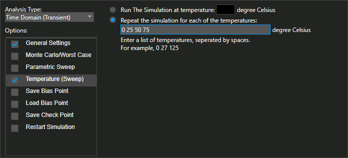
Step 12: The Temperature Sweep subpanel opens. Select the option to Repeat the Simulation for Each Temperature.
Step 13: Enter 0 25 50 75 into the temperature list text fields to run the simulation at ambient temperatures of 0°C, 25°C, 50°C, and 75°C.
Step 14: Click OK to save the settings and close the window.
Perform a Temperature Sweep: Placing Probes
Step 15: Before the simulation can be run, probes must be placed to define the parameters to plot. Select the Voltage/Level Marker button from the toolbar.
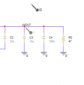
Step 16: Click to place a probe on the +VOUT net. Right-click and select End Mode.
Perform a Temperature Sweep in PSpice
Step 17: The simulation is ready to be run. Select PSpice > Run from the menu to start the simulation.
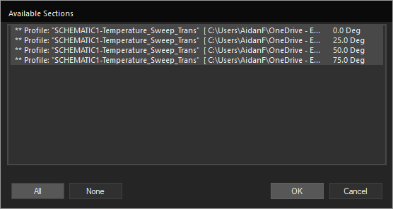
Step 18: When the simulation finishes, the PSpice A/D window opens to the Available Sections window. Here you can define which temperature sweeps to view data from. Choose All to select all sections and click OK.
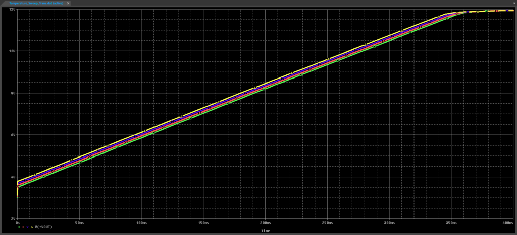
Step 19: View the simulation results. Each trace shows a different temperature. In this example, the green trace shows the simulation output when run at 0°C. The graph shows a linear increase in output voltage, indicating constant current, indicating that the MOSFET is operating in the saturation region. The saturation current is the same at each temperature but starts rising sooner at higher temperatures.
Perform a Parametric Temperature Sweep
Step 20: Close the PSpice A/D window.
Step 21: A finer temperature sweep with more runs can be performed as a parametric sweep. Back in the schematic, select PSpice > Edit Simulation Profile from the menu.
Step 22: The Simulation Settings window opens. Uncheck Temperature (sweep) and check Parametric Sweep.
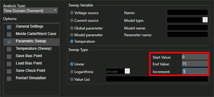
Step 23: The Parametric Sweep subpanel opens. Select Temperature for the Sweep Variable.
Step 24: Set the Sweep Type to Linear, the Start Value to 0, the End Value to 75, and the Increment to 5. This will sweep the ambient temperature from 0°C to 75°C in 5-degree increments.
Step 25: Click OK to save the settings and close the window.
Step 26: Select PSpice > Run from the menu to run the simulation.
Step 27: The Available Sections window opens to a much longer list of runs for each temperature. Select All and click OK.
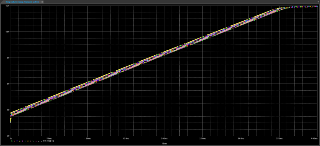
Step 28: View the results. The plotted trend is the same, a linear increase in output voltage with a lower starting point at lower ambient temperature.
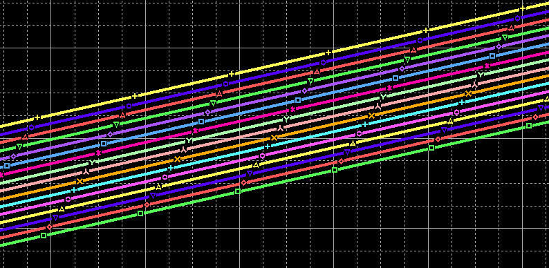
Note: Use the Zoom Area tool in the toolbar to zoom into the voltage increase for finer detail.
Wrap Up & Next Steps
Quickly and easily perform a temperature sweep in PSpice Designer to analyze circuit functionality in varying environmental conditions and ensure successful operation of your PCB. Test out this feature and more with a free trial of OrCAD. Want to learn more about PSpice? View additional how-tos, walk-throughs, and courses at EMA Academy.

