Incorporating flex elements into a design has become a common way to reduce required space, however, doing so increases the complexity of the PCB design. Rigid flex designs often require multiple stackups and constraint regions for proper fabrication. Additionally, rigid flex designs often have very tight tolerances and errors can be costly. For example, having a via or pin too close to a transition zone between two stackups can lead to cracking and splitting, and having a pad too close to a transition zone may cause peeling. OrCAD X Presto provides a quick and easy process to define inter-layer checks to get the rigid flex design right the first time.
This quick how-to will provide step-by-step instructions on how to perform inter-layer checks for rigid-flex PCB designs in OrCAD X Presto.
To follow along, download the provided files above the table of contents.
How-To Video
 Open in New Window
Enabling Inter-Layer Checks
Step 1: Open the provided design in OrCAD X Presto.
Step 2: Select Tools > Constraint Manager from the menu to activate the Constraint Manager.
Step 3: The Constraint Manager opens. Select Analyze > Analysis Mode from the Constraint Manager menu.
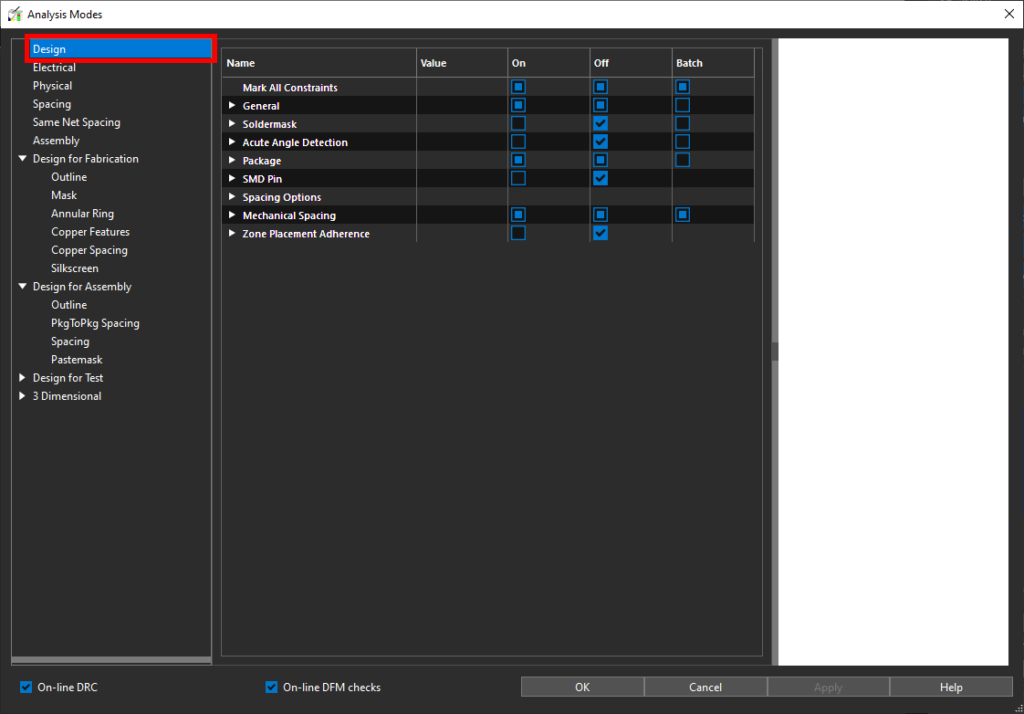
Step 4: The Analysis Modes window opens. Design rule checks are enabled and disabled from this window. Select Design from the mode table on the left side of the window.
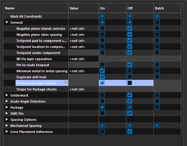
Step 5: Expand General. Select the checkbox under On for On-line InterLayer Checks to enable live inter-layer checks.
Step 6: Click OK to save the change and close the window. Minimize the Constraint Manager.
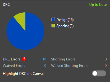
Step 7: In the Properties panel, in the DRC subpanel, select Refresh to refresh the DRCs. The DRC pie chart is updated with inter-layer check DRC errors.
Creating an Inter-Layer Check Rule
Step 8: Re-open the Constraint Manager.
Note: If you closed it earlier, select Tools > Constraint Manager from the menu.
Step 9: Select the Spacing domain from the Worksheet Selector.
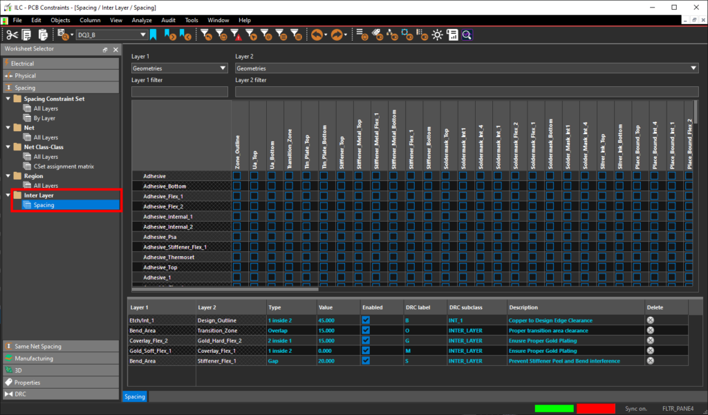
Step 10: Expand and select the Inter Layer > Spacing worksheet. The Inter-Layer Checks layer matrix and Rules Table opens.
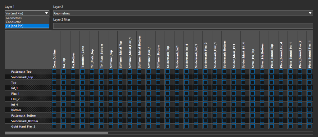
Step 11: For this example, we will create a rule to keep vias at least 12mil away from any transition area in the design to prevent potential cracking.
To create an inter-layer check rule, the relevant layers must be defined. Select Via (and Pin) from the Layer 1 menu. The subclass matrix is filtered to show etch subclasses for pins and vias under Layer 1.
Step 12: Enter tr into the Layer 2 filter field to filter the matrix to include only subclasses with “tr” in the name. In this case, this is only the Transition_Zone subclass.
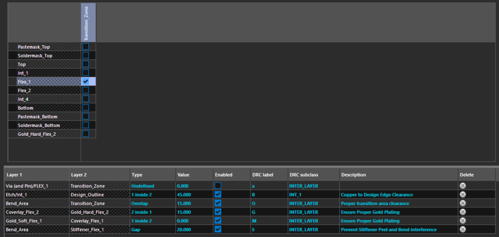
Step 13: Check the box at the intersection of the Transition_Zone subclass and layer Flex_1. A new rule entry is added to the Rules Table.
Defining the Rule Entry
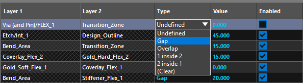
Step 14: In the Rules Table, select the Type cell for the new rule and select Gap from the drop-down menu. This will set the type of check to Gap, which requires spacing between the Layer 1 and Layer 2 subclasses.
Step 15: Enter 12 for the value.
Step 16: Check the box in the Enabled column to allow the DRC system to recognize and activate this rule.
Step 17: Enter t for the DRC Label to assist in visual recognition of a violation of this rule.
Note: Lowercase “a” is the default value. Allowable characters are “a” through “z,” “A” through “Z,” and “0” through “9.” The first DRC character “I” is fixed to indicate an inter-layer DRC rule violation.
Step 18: The layer the marker is displayed on can be assigned to this rule. Select FLEX_1 from the DRC Subclass dropdown.
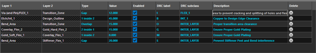
Step 19: Lastly, enter a description for the rule. For this example, enter Via and pin to transition area to prevent cracking and splitting of holes and flex.
Step 20: The rule is defined and will be checked as part of the standard design rule check. Close the Constraint Manager.
Perform Inter-Layer Checks
Step 21: To view the violation of the new rule, select Visibility on the left side of the screen to open the Visibility panel.
Note: If there is no Visibility button on the left side of the screen, select View > Panels > Visibility from the menu.
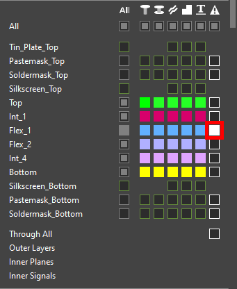
Step 22: In the Layers mode, click the button to activate visibility for DRCs for Flex_1.
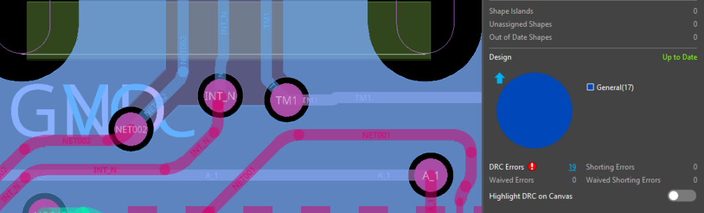
Step 23: The DRC cache must be updated again. Select Refresh in the DRC subpanel of the Properties panel. 19 design errors are now listed.
Step 24: Select the Design section of the pie chart to filter the DRC list to just design errors which include inter-layer check errors.
Step 25: The search panel opens at the bottom of the screen. View the DRC errors in the Design domain.
Step 26: Hover over the DRC Subclass column header in the Search panel and select the Filter icon.
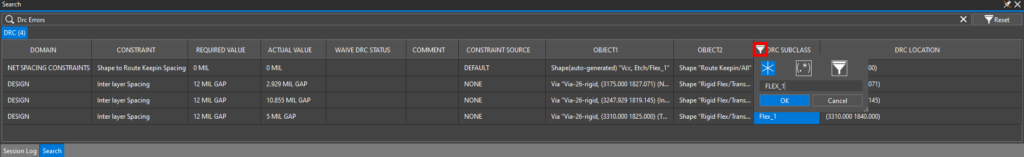
Step 27: The Filter widget opens with the Wildcard mode selected automatically. Enter FLEX_1 for the wildcard term and click OK. The list is filtered to four errors in the FLEX_1 subclass, including three generated from the new inter-layer check rule.
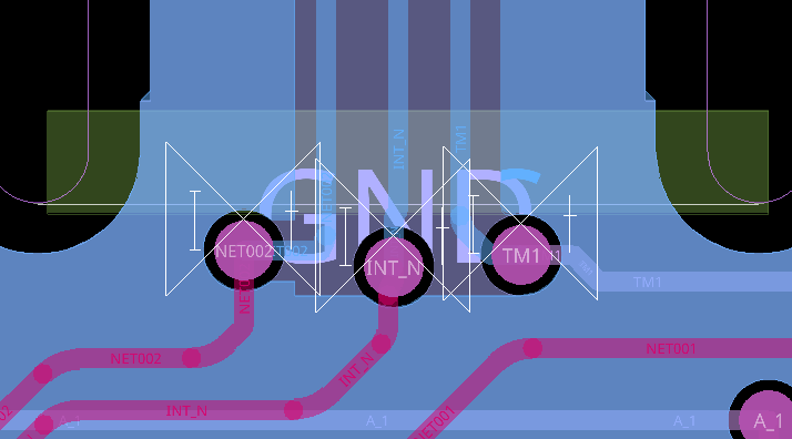
Step 28: Double-click one of the errors whose required value is 12mil to be brought to its location on the board. Three via-in-transition-zone violations are shown with DRC markers labeled “I-t,” as defined in the Rules Table.
Correcting the Violations

Step 29: The violations can be corrected by sliding the affected vias. Select the Slide mode from the toolbar.
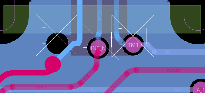
Step 30: Click a via to select it. Move the mouse to adjust the via position and click again to place. Adjust the three vias such that they are sufficiently spaced from the transition zone (shown in green).
Step 31: When finished, choose the Select mode from the toolbar.
Step 32: Select Refresh in the DRC subpanel again. The error markers are removed, indicating that the vias are no longer in violation of the rule.
Note: If the number of Out of Date Shapes is greater than 0, select Refresh for Out of Date Shapes first.
Wrap Up & Next Steps
Quickly perform inter-layer checks to prevent costly errors such as peeling and cracking and ensure reliability for rigid-flex designs with the Constraint Manager in OrCAD X Presto. To test this feature and more, get a free trial of OrCAD. Want to learn more about OrCAD X Presto? Check out our other how-tos and step-by-step walk-throughs at EMA Academy.

