With the number of connections on a PCB, routing must be optimized to complete the PCB layout efficiently. The Add Connect command can be used to quickly route connections in OrCAD X Presto and covers the majority of a designer’s routing needs including:
- Drawing manual connections
- Drawing differential pair connections
- Specifying connection voltages
- Auto-interactive routing
- Trace settings and options
- Group routing configurations
- Automatic smoothing and centering options
- Advanced settings for clearance views, working layers, and more
This quick how-to will provide step-by-step instructions on how to route connections in OrCAD X Presto with the Add Connect command.
How-To Video
 Open in New Window
Configuring the Add Connect Command
Step 1: Open the desired design in OrCAD X Presto.
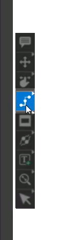
Step 2: Select the Add Connect mode from the toolbar.
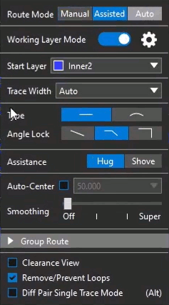
Step 3: A widget appears on the canvas with properties to adjust the behavior of the command. Click and drag the widget to move it to the optimal position.
Step 4: To hide the widget, select the Add Connect tab at the top of the canvas or press X on the keyboard. To re-enable it, select the tab again.
Note: Press X to show the widget at your cursor for quick access.
Manually Route Connections in OrCAD X Presto
Step 5: Select the Manual tab.
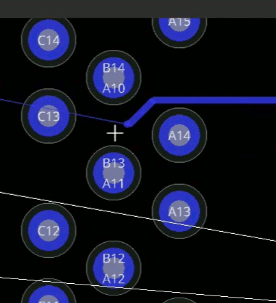
Step 6: Click a connection to start routing then click the end connection.
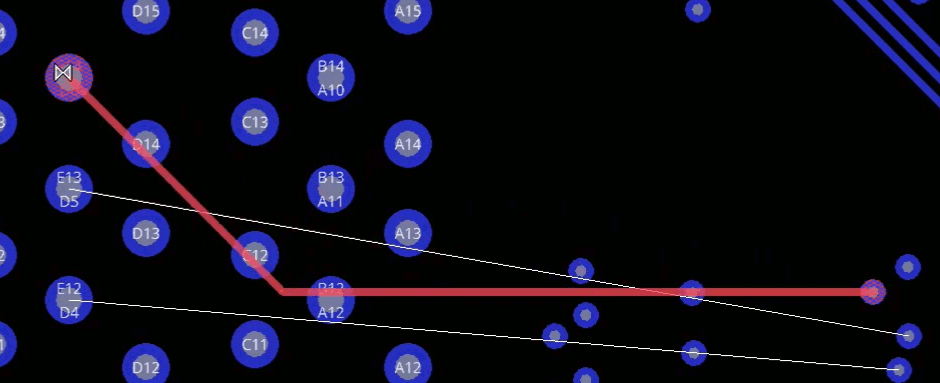
Note: The trace will turn red to indicate potential issues. Since Manual mode is selected, the trace will be placed, and a DRC marker will be created.
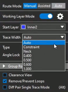
Step 7: In the Add Connect widget, select the desired trace width from the Trace Width dropdown or manually type the desired width into the dropdown.
Note: The following options are available by default:
- Auto
- If starting from a pad or via, uses the values defined in the constraint manager
- If starting from a trace segment, inherits the trace width of that trace.
- Constraint: Uses the values defined in the constraint manager
- Neck: Uses the neck values defined in the constraint manager
Step 8: Select 0.300 from the Trace Width menu.
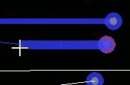
Step 9: Click to start drawing a trace from a via. The trace width is 0.3mm. Click to connect the trace to its destination.
Note: Double-click to end the trace routing anywhere on the board.
Step 10: Select Auto from the Trace Width menu.
Step 11: Click to start routing from another via. The trace width has returned to the constraint value. Click to connect the trace to its destination.
Step 12: Click to start routing from the 0.3mm trace. The trace width is 0.3mm.
Route Connections in OrCAD X Presto with Arcs
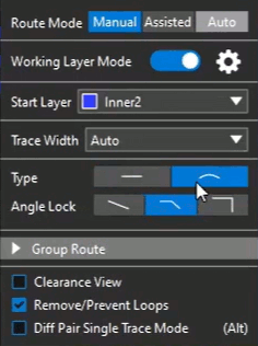
Step 13: Select Arc from the Type options to route traces as arcs.
Step 14: Set the Angle Lock to 0 degrees.

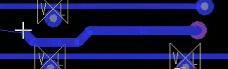
Step 15: Select a starting point for the trace. Click the PCB canvas to route a smooth trace. Click to finish the trace. Instead of sharp bends, the trace is now routed in smooth arcs.
Using Clearance View to Route Connections in OrCAD X Presto
Note: Clearance view assists in finding channels for routing.
Step 16: Check Clearance View in the Add Connect widget to enable Clearance View.
Step 17: Click a via or pin to start routing a trace. Bumpers are now visible around any copper features as per spacing constraints. Click to route and finish the trace.
Using Assisted Mode to Route Connections in OrCAD X Presto
Step 18: Select Assisted for the Route Mode from the Add Connect widget.
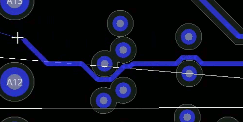
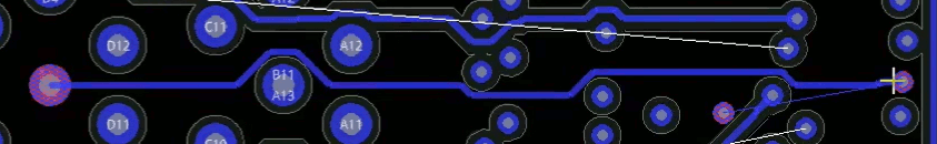
Step 19: Click a via or pin to start routing a trace. Presto will use the Hug or Shove mode to route without triggering a DRC error. Click to route and finish the trace.
Note: In the Hug mode, the trace will automatically route around copper features as close as it can without violating the constraint. In the Shove mode, the trace will push other traces to prevent any errors. An option is available to shove vias as well. Clearance view is not recommended in Shove mode, as copper features on other layers may move.
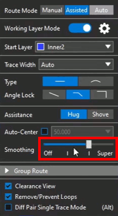
Step 20: Enable smoothing by dragging the Smoothing slider in the Add Connect widget towards Super.
Note: The number of vertices on routed traces is reduced, making routing simpler.
Wrap Up & Next Steps
Quickly route connections with manual routing, assisted routing, and an easy-to-use interface with visual graphics to complete your PCB layout in OrCAD X Presto. Test out this feature and more with a free trial of OrCAD X Presto. For more how-tos and step-by-step walk-throughs, visit EMA Academy.
