Configuring Constraints
This lesson will demonstrate how to configure and assign design rules in OrCAD X Presto. Rules or constraints dictate how critical aspects of the design should be completed. Setting design rules upfront can be used to:
- Adhere to device design requirements
- Guarantee proper functionality
- Ensure safety
- Improve signal integrity
- Adhere to manufacturer’s capabilities and requirements
- Verify the PCB assembly
To follow along, continue with the design from the previous lesson or download the starting materials from the Materials tab of this lesson.
 Open in New Window
Defining Differential Pairs
Note: Differential pairs have already been defined in this design. For the purpose of this lesson, we will delete a differential pair and redefine it.
Step 1: Select Tools > Constraint Manager from the menu.
Step 2: Select the Electrical domain from the Worksheet Selector.
Step 3: Select the Net > Routing > Differential Pair worksheet.
Step 4: Right-click differential pair DPD and select Delete. Click Yes when prompted to delete the differential pair.
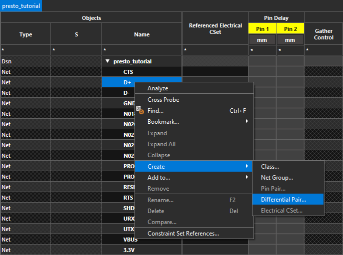
Step 5: Right-click net D+ and select Create > Differential Pair.
Step 6: The Create Differential Pair window opens. Select Net from the dropdown on top.
Step 7: Select D- from the net list and click the > symbol to add it to the differential pair.
Note: The Auto Setup functionality can also be used to automatically identify and create differential pairs within the design.
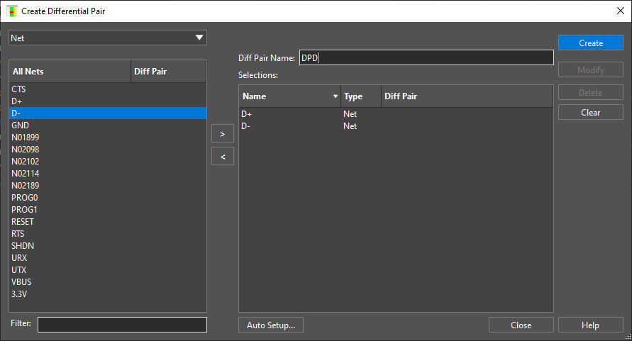
Step 8: Enter DPD for the Diff Pair Name and click Create.
Step 9: Click Close to close the Create Differential Pair window.
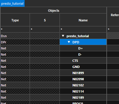
Nets D+ and D- are now grouped in differential pair DPD indicated by Dpr in the constraint manager window.
Defining Physical Constraints
Step 10: Select the Physical domain from the Worksheet Selector.
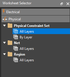
Step 11: Expand the Physical Constraint Set folder and select the All Layers worksheet.
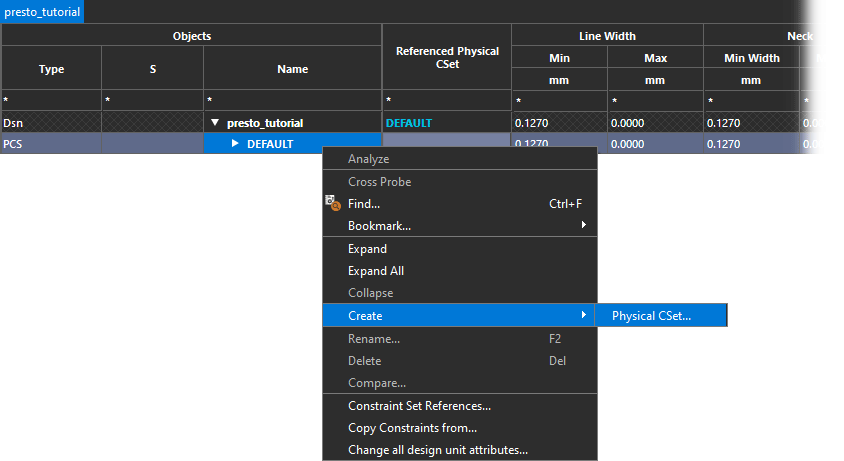
Step 12: Right-click the DEFAULT constraint set and select Create > Physical CSet.
Step 13: Name the CSet POWER_GND and click OK.
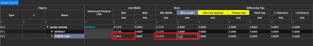
Step 14: Enter the following values for the new CSet under their respective columns.
- Minimum Line Width: 0.381
- Minimum Neck Width: 0.127
- Maximum Neck Length: 5.08
Step 15: Right-click the DEFAULT constraint set and select Create > Physical CSet.
Step 16: Name the constraint set DP and click OK. This will create a group of rules for the differential pairs in the design.
Step 17: Enter the following constraint values for the new CSet under their respective columns.
- Minimum Line Width: 0.127
- Primary Gap: 0.127
Assigning Physical Constraints
Step 18: Select the Net > All Layers worksheet in the Physical domain.
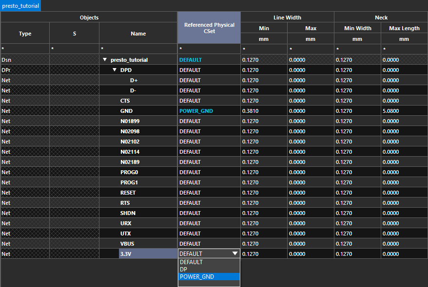
Step 19: Select the POWER_GND CSet from the dropdown in the Referenced Physical CSet column for 3.3V and GND.
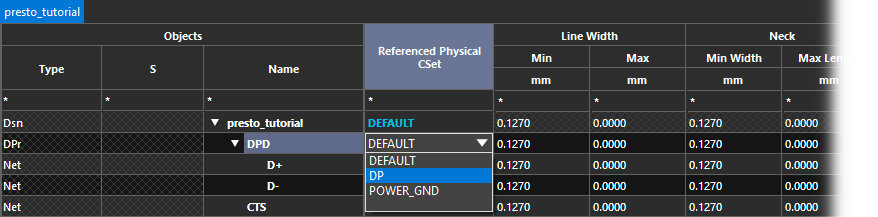
Step 20: Select the DP CSet from the dropdown in the Referenced Physical CSet column for DPD.
Note: Assigning this CSet at the top level will assign it to each net of the differential pair.
Defining Electrical Constraints
Step 21: Select the Electrical domain from the Worksheet Selector.
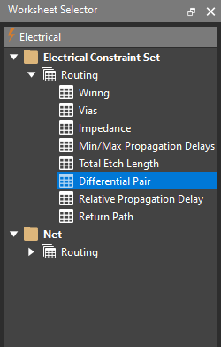
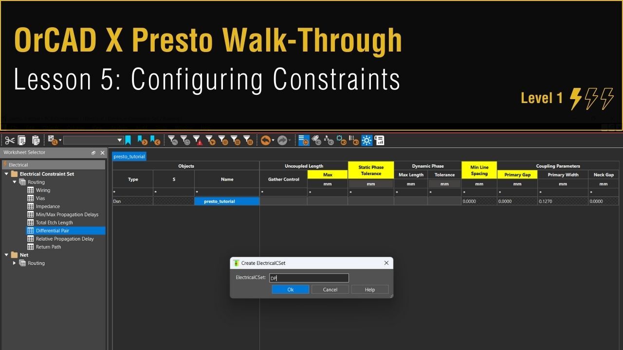
Step 22: Select the Electrical Constraint Set > Routing > Differential Pair worksheet.
Step 23: Right-click in the table and select Create > Electrical CSet.
Step 24: Name the CSet DP and click OK.
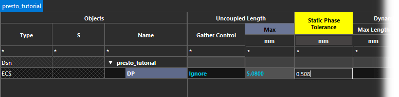
Step 25: Enter the following values for the new constraint set under their respective columns.
- Gather Control: Ignore
- Max Uncoupled Length: 5.08
- Static Phase Tolerance: 0.508
Step 26: Expand the Net > Routing > Differential Pair worksheet.
Step 27: Select the DP CSet from the dropdown in the Referenced Electrical CSet column for DPD.
Defining 3D Constraints
Step 28: Select the 3D domain from the Worksheet Selector.
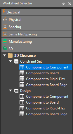
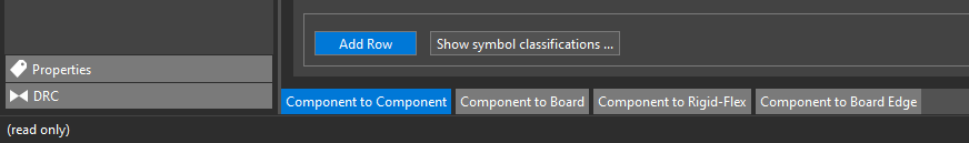
Step 29: Expand 3D Clearance > Constraint Set and select the Component to Component worksheet.
Step 30: Select the plus sign to create a new CSet.
Step 31: Name the CSet PKG2PKG and click OK.
Step 32: Select Add Row to add a row to the CSet.
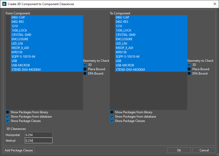
Step 33: The Create Clearances window opens. Click and drag to select all items in the From Component and To Component tables.
Step 34: Enter 0.254 for the Horizontal and Vertical 3D Clearances. Click OK. The clearances are added to the table automatically.
Step 35: Select the 3D Clearance > Design > Component to Component worksheet.
Step 36: For presto_tutorial, under Referenced Package to Package 3D CSet, select PKG2PKG from the dropdown.
Assigning Net Voltages
Step 37: Select the Properties domain in the Worksheet Selector.
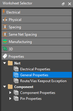
Step 38: Select the Net > General Properties worksheet.
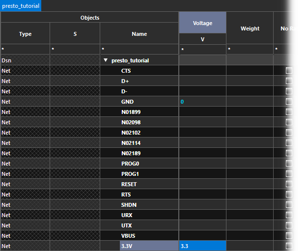
Step 39: In the Voltage column, assign 0 to GND and 3.3 to 3.3V.
Step 40: Close the Constraint Manager.
Confirming the Constraints
Step 41: Back in the Presto canvas, in the Properties panel, select All Objects under Selection Filter to turn all objects off.
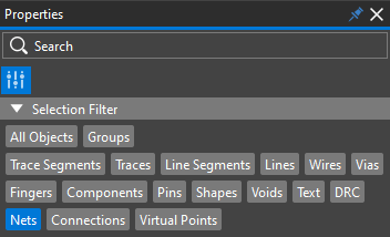
Step 42: Select Nets to filter only net objects.
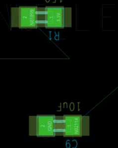
Step 43: Select a 3.3V net. Instead of ratsnest lines, all nets with a voltage assigned have a square with an “X” for easy identification.
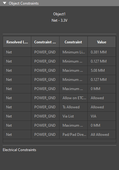
Step 44: Select the Constraints mode in the Properties panel. The constraints for 3.3V are shown.
Step 45: Select net D+ from X1 or IC1. The physical and electrical constraints for the differential pair are shown.