While the model libraries included in OrCAD PSpice are extensive, they don’t evolve with the introduction of new electrical components. To keep up with these new additions, many manufacturers provide models for their components so an accurate circuit simulation can be produced. Easily import 3rd party models and generate the required format for simulation with PSpice.
This how-to will provide step-by-step instructions for importing 3rd party simulation models in text file format and .lib file format.
To follow along, download the provided files above the table of contents.
Simulation Models in .lib Format
This section of the how-to will provide instructions on importing a .lib model file into PSpice for simulation.
Opening a PSpice Library
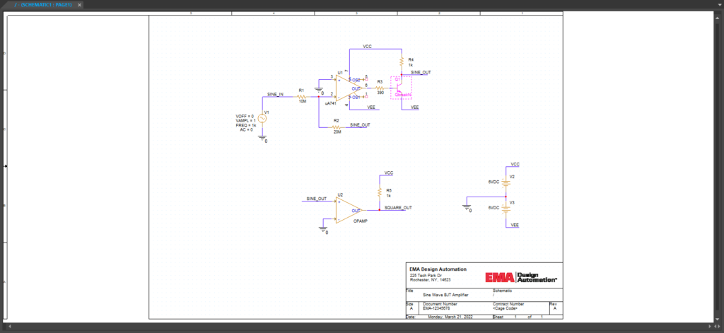
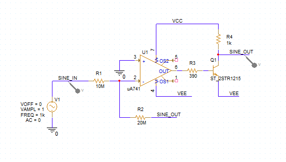
Step 1: Open the provided design, SineAmp.dsn, in OrCAD PSpice Designer.
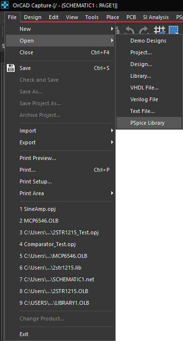
Step 2: Select File > Open > PSpice Library from the menu.
Step 3: Navigate to the 2STR1215.lib file included in the provided files and open it.
Note: Any .lib files downloaded from outside sources must be modified and configured for PSpice. Therefore, the 2STR1215.lib file must be modified as well to be usable.
Using PSpice Model Editor
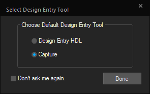
Step 4: The PSpice Model Editor will open as well as the Select Design Entry Tool window. Select Capture and choose Done.
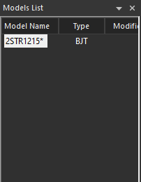
Step 5: From the Models List on the left, select 2STR1215.
Step 6: The SPICE model file will open. To the right of .MODEL is the name of the part. Change it to ST_2STR1215.
Note: PSpice will not run the simulation if the part name starts with a number.
Step 7: Save the file and close the Model Editor. Return to Capture.
Associating a PSpice Model
Step 8: Select transistor Q1.
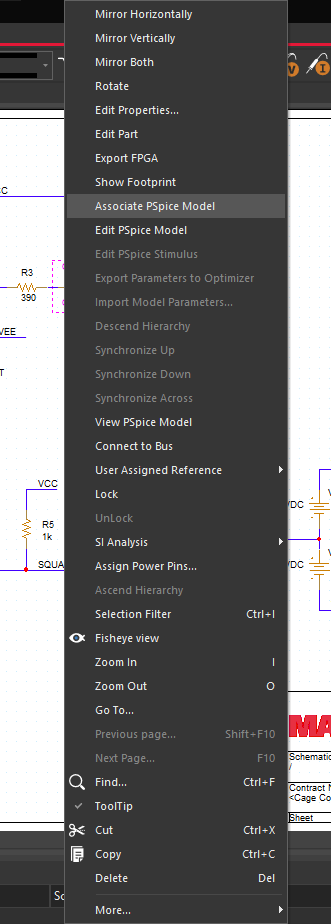
Step 9: Right-click and select Associate PSpice Model.
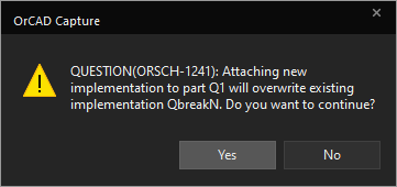
Step 10: A prompt will appear. Select Yes to overwrite the existing model and open the Associate PSpice Model window.
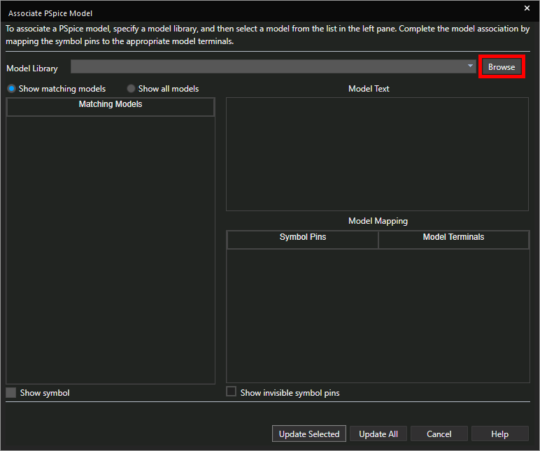
Step 11: To the right of the Model Library drop-down, select Browse.
Step 12: Browse to the location of 2STR1215.lib. Select and open the file.
Note: ST_2STR1215 will be selected automatically.
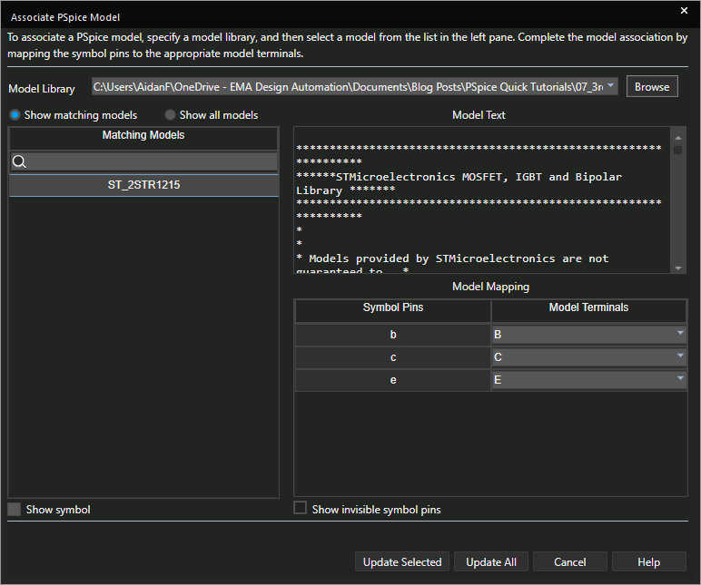
Step 13: In the Model Mapping table, confirm that symbol pins b, c, and e match with model terminals B, C, and E.
Note: If model terminals are not mapped correctly, modify the mapping with the drop-down selection.
Step 14: Select Update Selected to update the part.
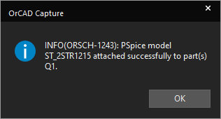
Step 15: A message will appear saying that the model association was successful. Click OK.
Creating a PSpice Simulation Profile
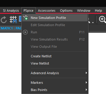
Step 16: Select PSpice > New Simulation Profile from the menu.
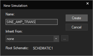
Step 17: Name the simulation SINE_AMP_TRANS. Set Inherit From to none and click Create.
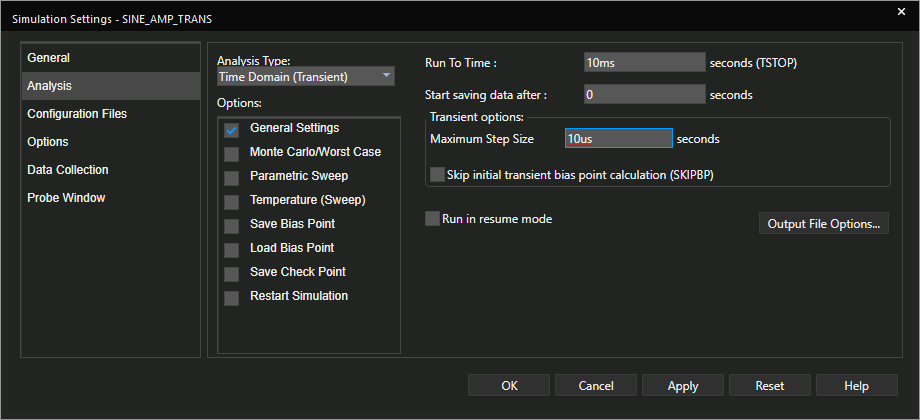
Step 18: Set the Run To Time to 10ms and the Maximum Step Size to 10us.
Associating the PSpice Model Library
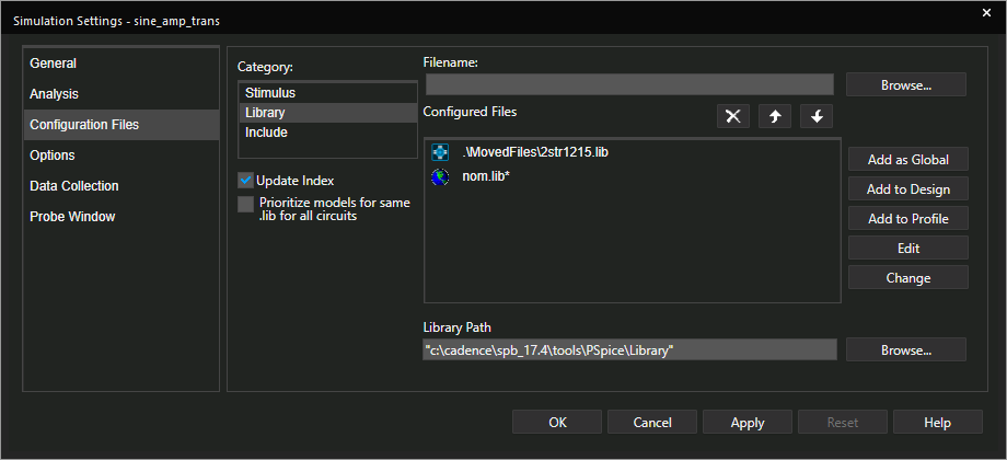
Step 19: Select Configuration Files from the sidebar.
Step 20: Select Library under Category.
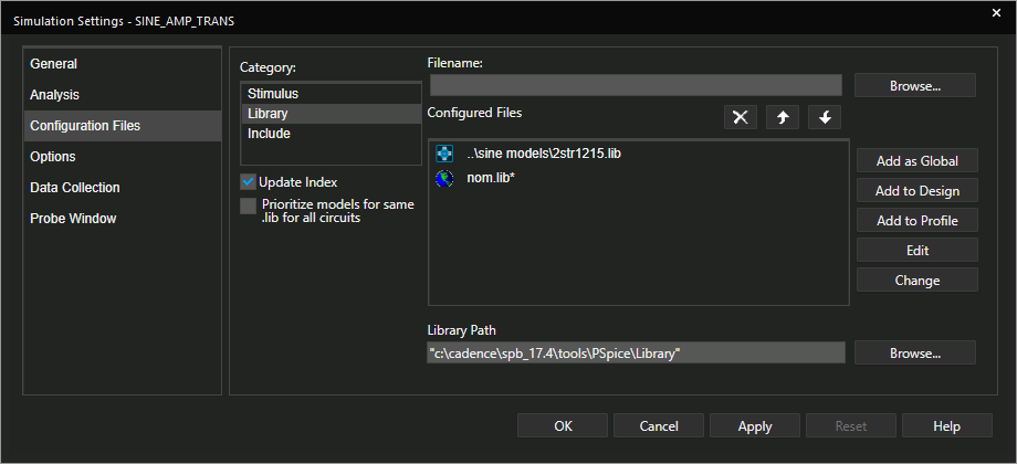
Step 21: Confirm that the 2STR1215.lib file exists in the Configured Files list.
Note: If only the nom.lib file is shown, perform the following steps.
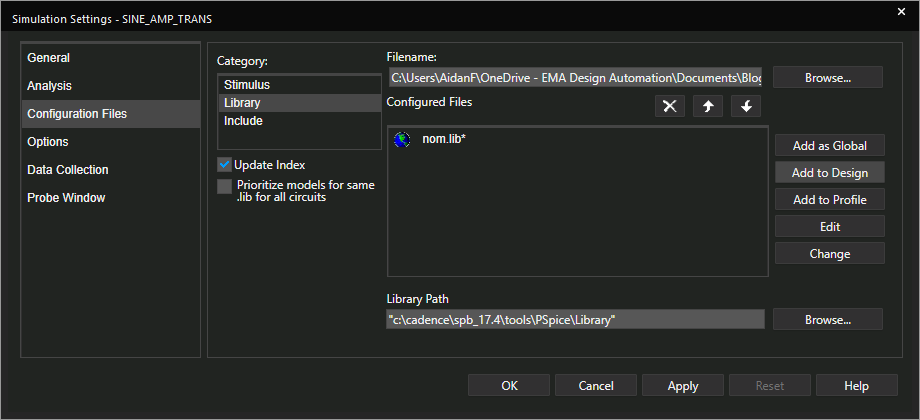
- Select Browse.
- Browse to the location of 2STR1215.lib. Select the file.
- Select Add to Design.
Step 22: Click OK to save the simulation profile.
Performing a PSpice Simulation
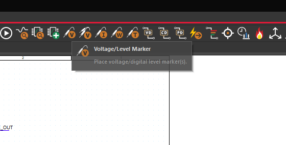
Step 23: Select the Voltage/Level Marker button from the toolbar to place a probe.
Step 24: Click to place a probe on the SINE_IN net and another on the SINE_OUT net. Right-click and select End Mode.
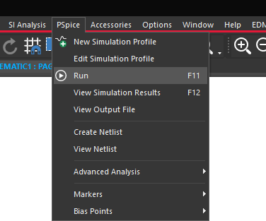
Step 25: Select PSpice > Run from the menu or the Run button on the toolbar.
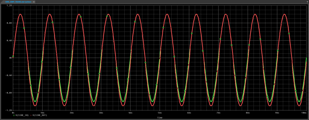
Step 26: View the simulation results.
Simulation Models in .txt Format
3rd party simulation models can be sources from many manufacturers. These models are often provide in various formats. This section of the how-to will provide instructions on how to import a .txt model file for simulation in PSpice.
Note: This process can be completed for any simulation model format.
Renaming the 3rd Party File
Step 1: Right-click on the MCP6547.txt file from the provided files and select Rename.
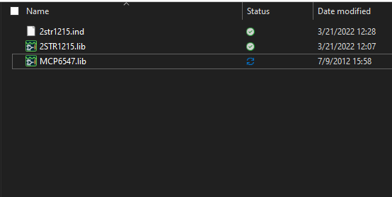
Step 2: Change the extension to .lib.
Note: The extension must be written in lowercase letters to be able to run in PSpice. PSpice will not recognize .LIB.
Creating a PSpice Model
Step 3: Open the PSpice Model Editor. To do so, open the Start menu and select Cadence PCB Utilities 17.4-2019 > PSpice Model Editor 17.4.
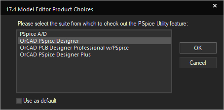
Note: If the Model Editor Product Choices window opens, select OrCAD PSpice Designer and click OK.
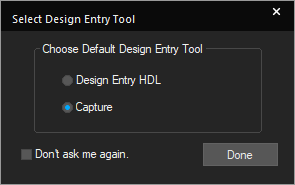
Step 4: The Select Design Entry Tool window will open. Select Capture and choose Done.
Using Model Import Wizard
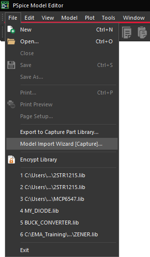
Step 5: Select File > Model Import Wizard [Capture] from the menu.
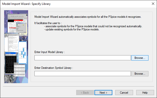
Step 6: The Model Import Wizard will open. Select Browse next to Enter Import Model Library.
Step 7: Navigate to the MCP6547.lib file, select it and click Open.
Note: The Destination Symbol Library path will be filled out automatically. To save the file elsewhere, click Browse and browse to the desired location to save the symbol library file.
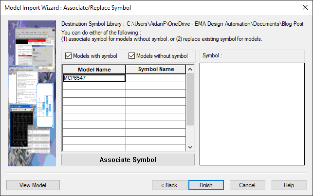
Step 8: Select Next. This will open the Associate/Replace Symbol table. There is no symbol associated this model.
Note: If no symbol is selected, the schematic symbol will be a rectangular symbol with pins organized in columns. To learn how to create a custom schematic symbol for a new PSpice model, view the blog instructions here.
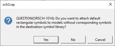
Step 9: Select Finish. A prompt will appear asking to attach the default rectangular symbol to models without an associated symbol. Select Yes.
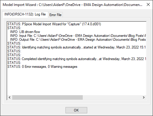
Step 10: A log file will open with any errors that may have occurred. Click OK. Close the Model Editor.
Placing a New PSpice Model
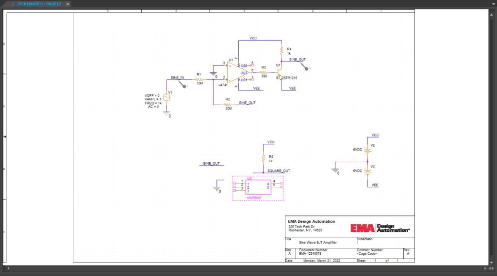
Step 11: Open the provided design, SineAmp2.dsn, in OrCAD PSpice Designer.
Step 12: Select the existing op-amp U2 and press Delete on the keyboard.
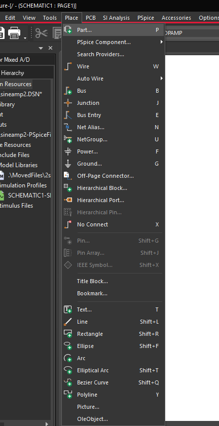
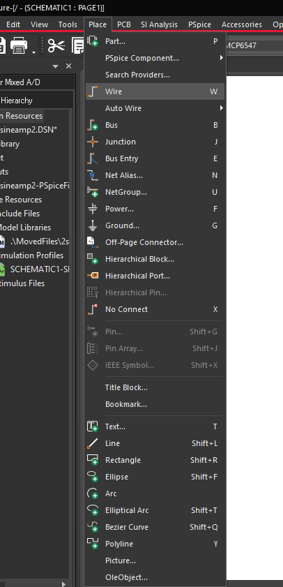
Step 13: Select Place > Part from the menu or click the Place Part button on the toolbar.
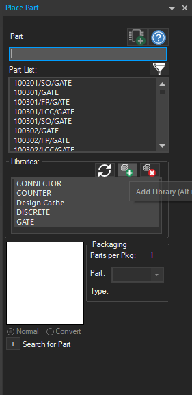
Step 14: Select the Add Library button.
Step 15: Browse to the saved symbol library. Select it and click Open.
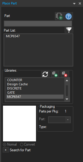
Step 16: In the Libraries table, scroll down and select MCP6547. The newly-created part will appear in the Part List.
Step 17: Select the part and click Place Part. Click to place the part in the schematic canvas. Right-click and select End Mode.
Simulation with 3rd Party Models
Step 18: Select Place > Wire from the menu, the Wire button on the toolbar, or press W on the keyboard.
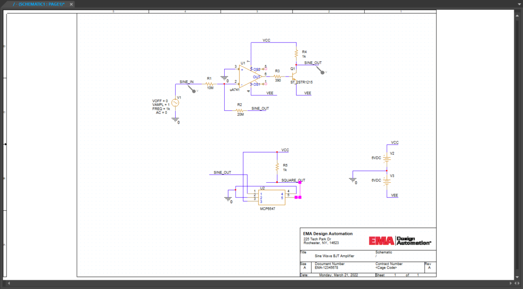
Step 19: Wire the connections to each pin of the comparator as shown above. Press Escape on the keyboard when finished.
Step 20: Select the Voltage/Level Marker button from the toolbar.
Step 21: Click to place a probe on the SQUARE_OUT net. Right-click and select End Mode.
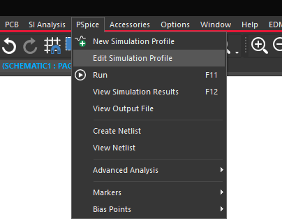
Step 22: Select PSpice > Edit Simulation Profile from the menu.
Step 23: Select Configuration Files from the sidebar.
Step 24: Select Library under Category.
Step 25: Select Browse. Navigate to the MCP6547.lib file, select it and click Open.
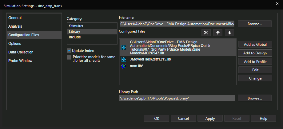
Step 26: Select Add to Design.
Note: If libraries are not configured, the simulation will not run. Select Add to Global to configure the file for all future simulations.
Step 27: Click OK to save the simulation settings and close the window.
Step 28: Select PSpice > Run from the menu.
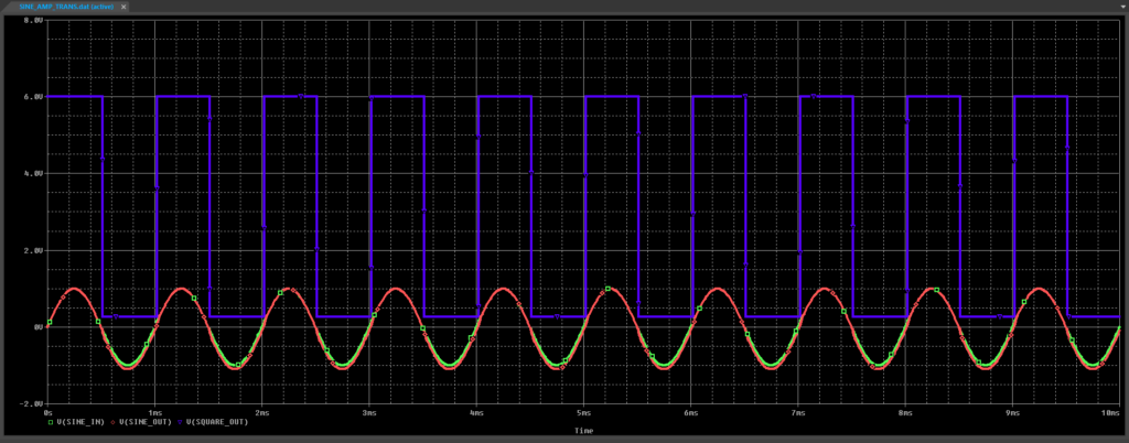
Step 29: View the simulation results.
Wrap Up & Next Steps
Many manufacturers provide simulation models for components, but file formats often vary. Quickly import and configure models from manufacturers to perform accurate analysis of circuit behavior with the Model Editor in OrCAD PSpice. Learn more about the functionality included in OrCAD PSpice and test them out yourself with a free trial.

