Often, circuit analysis requires detailed measurements to understand specific circuit behavior and verify design functionality. These measurements can be time consuming and tedious to set up. Saving measurements and display settings from previous simulations with PSpice Designer expedites circuit analysis.
This how-to will provide step-by-step instructions for:
- Viewing a simulation with the same settings as the previous simulation
- Saving Measurements
- Saving Traces Displayed in PSpice Results
- Creating a template containing display settings and measurements
- Applying a template for quick analysis of results for future simulations
To follow along with this tutorial, download the provided files above the table of contents.
How-To Video
Performing a PSpice Simulation
Step 1: Open the provided design, Boost_Converter.opj, in OrCAD PSpice Designer.
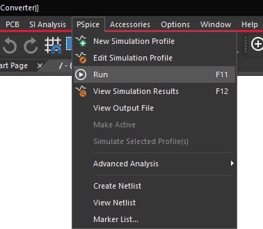
Step 2: Select PSpice > Run from the menu or the Run button on the toolbar.
Step 3: View the result window.
Note: The simulation plot is blank as there are no probes placed in the schematic nor any trace expressions added to the plot.
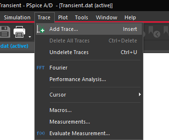
Step 4: Select Trace > Add Trace from the menu.
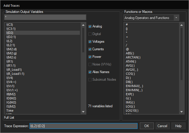
Step 5: From the Simulation Output Variables list, select I(L2) and I(D2). Click OK.
Adding Measurements
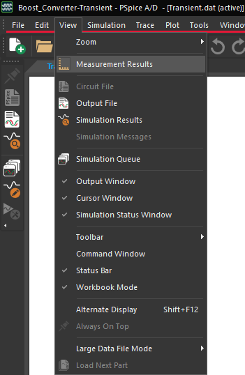
Step 6: Select View > Measurement Results from the menu. This will open the Measurement Results pane.
Note: If the Measurements Results are not visible, close the Output Window.
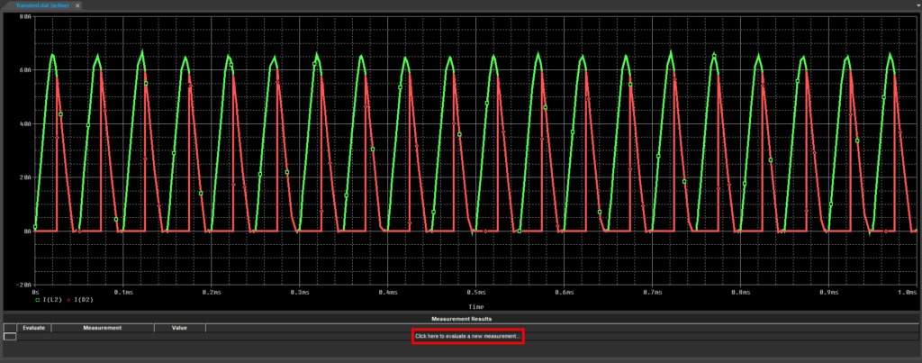
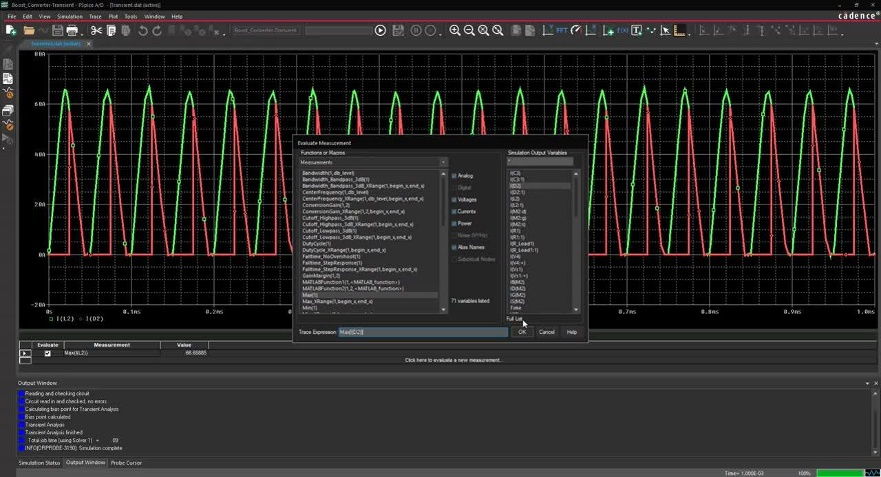
Step 7: Select Click here to evaluate a new measurement. This will open the Evaluate Measurement window.
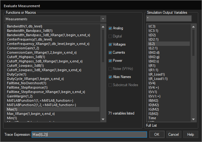
Step 8: From the Functions or Macros dropdown, select Measurements. Select Max(1).
Step 9: From the Simulation Output Variables list, select I(L2).
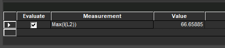
Step 10: Click OK. The trace expression has been added.
Step 11: Select Click here to evaluate a new measurement again to add a new measurement.
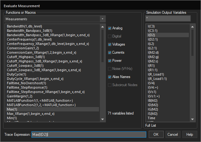
Step 12: From the Functions or Macros dropdown, select Measurements. Select Max(1).
Step 13: From the Simulation Output Variables list, select I(D2).
Step 14: Click OK. The trace expression has been added.
Saving Plot Settings
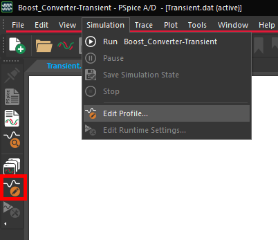
Step 15: Select Simulation > Edit Profile from the menu or the Edit Simulation Settings button from the sidebar.
Step 16: Select Probe Window from the menu on the left.
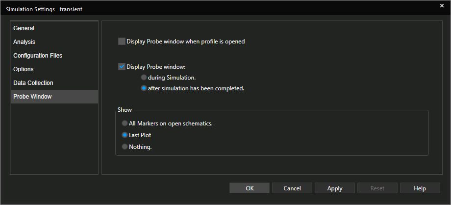
Step 17: Select Last Plot under Show. Click OK.
Note: This will automatically configure the results window for the next simulation run to contain the display settings currently visible.
Step 18: Close out of the simulation.
Modifying the Simulation
Step 19: Double-click the value of Vs1, 40Vdc, to change it.
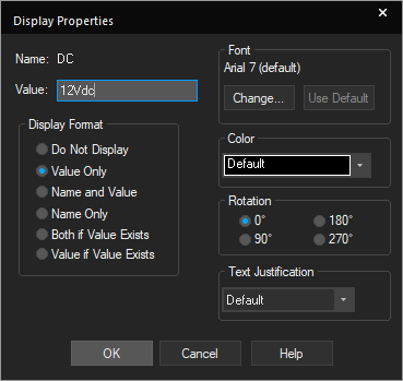
Step 20: Change the value to 12Vdc. Click OK.
Step 21: Select PSpice > Run from the menu or the Run button on the toolbar.
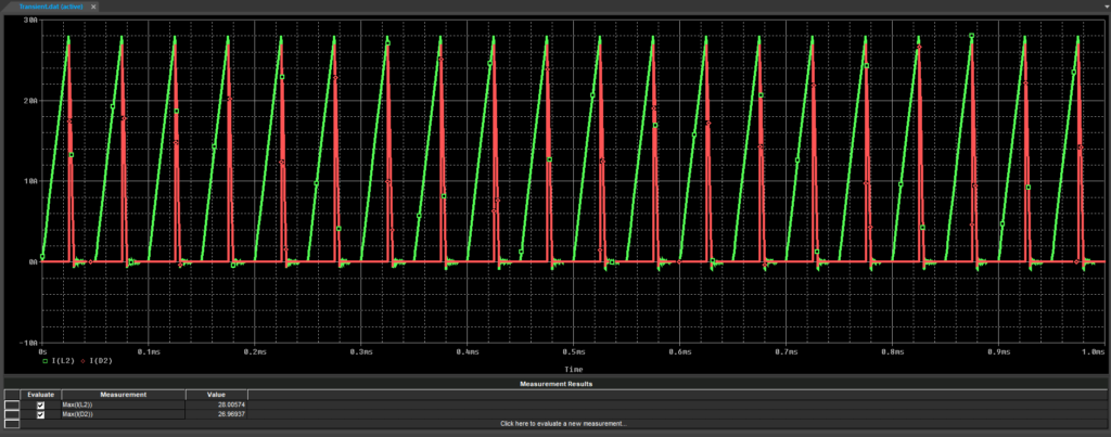
Step 22: View the results.
Note: The same trace expressions, I(L2) and I(D2), have been automatically added to the plot.
Saving Measurements and Displays
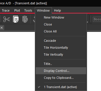
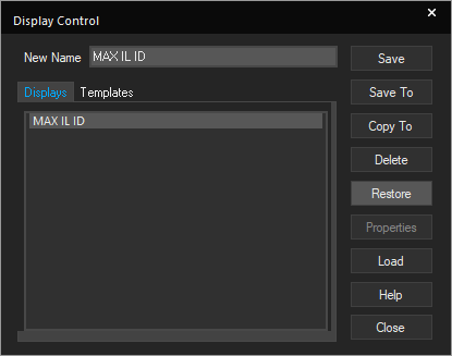
Step 23: To create a template containing the current display settings and measurements to be applied to future simulations, select Window > Display Control from the menu. The Display Control window will open.
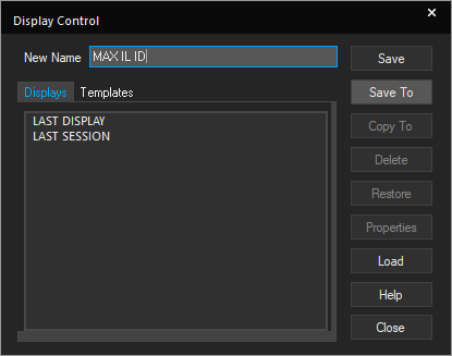
Step 24: Enter MAX IL ID as the name. Select Save To.
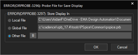
Step 25: Choose Other File and select the B to browse.
Step 26: Browse to a location to save the file. Name the file MAX IL ID and select Open. Click OK.
Step 27: Select Close to close the Display Control window and close out of the simulation.
Opening a New PSpice Design
Step 28: Back in the schematic, close out of boost_converter.opj. Select No to All when prompted.
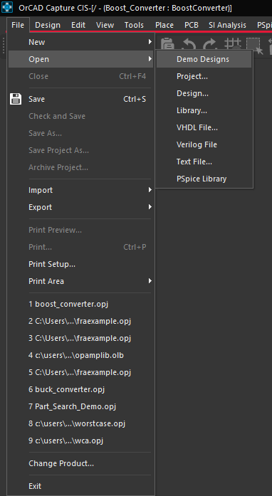
Step 29: Select File > Open > Demo Designs from the menu.
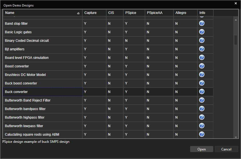
Step 30: Scroll down and select Buck Converter. Click Open.
Step 31: Select PSpice > Run from the menu or the Run button on the toolbar.
Applying a Plot Template
Step 32: In the simulation window, select Window > Display Control.
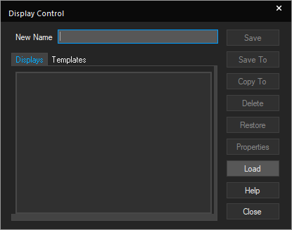
Step 33: In the Display Control window, select Load.
Step 34: Browse to the saved MAX IL ID.prb file and select it. Select Open.
Step 35: Select the MAX IL ID entry added to the display list and click Restore.
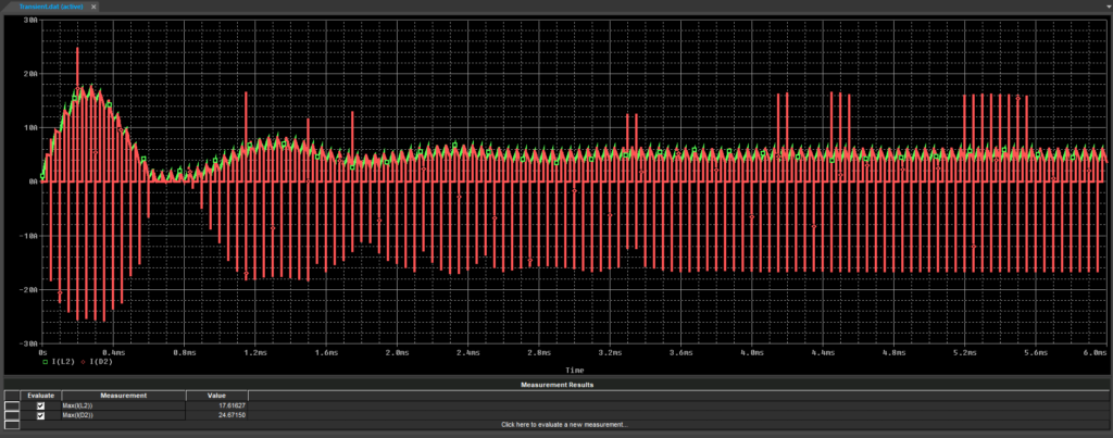
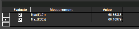
Step 36: View the results. Max(I(L2)) and Max(I(D2)) have been added to the Measurement Results pane, and I(L2) & I(D2) have been added as traces.
Note: If the Measurements Results are not visible, close out of the Output Window.
Wrap Up & Next Steps
Expedite analysis of circuit simulations by creating templates, saving measurements and display settings for future analysis with OrCAD PSpice Designer. Learn more about PSpice and get your free trial of OrCAD.

