Reference designators are unique identifiers assigned to each component in a schematic design and are required to clearly label and track components throughout the PCB design and manufacturing process. It is vital that PCB designers assign reference designators to aid in component identification, cross-probing between schematic and layout, BOM generation, assembly, testing, and debugging. Ensuring reference designators are unique and consistent throughout the design and following standard prefixes for component types can be time consuming for large designs. OrCAD X Capture allows designers to automatically assign reference designators to save time, prevent errors, and increase consistency.
This quick how-to will provide step-by-step instructions on how to automatically assign reference designators with annotation in OrCAD X Capture.
To follow along, download the provided files above the table of contents.
How-To Video
 Open in New Window
Adding Reference Designators Manually
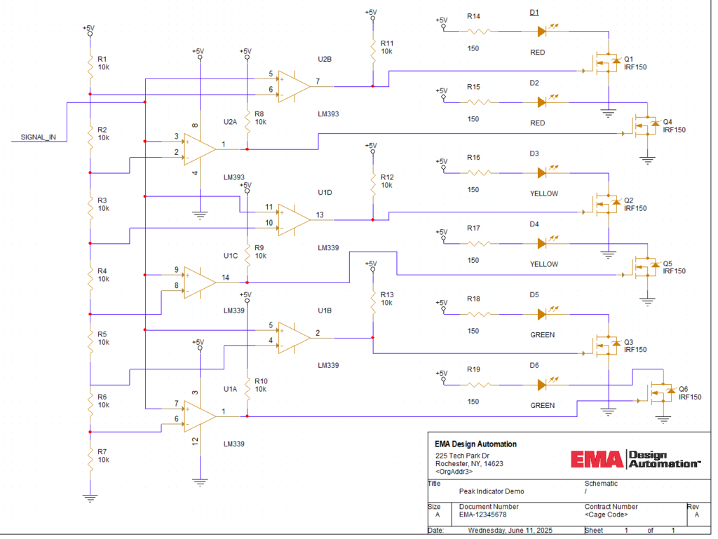
Step 1: Open the provided design in OrCAD X Capture.
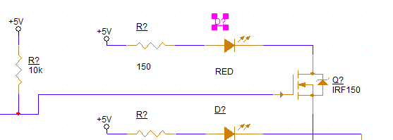
Step 2: The schematic canvas opens to show all resistors, diodes, and transistors in the design to have unassigned reference designators. To assign a designator manually, double-click the designator. Double-click the designator for the uppermost LED.
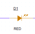
Step 3: The Display Properties window opens for the reference designator. Here you can define the value and how it is displayed in the schematic. Enter D1 for the name and click OK.
Step 4: View the schematic. The reference designator has been changed to D1.
Note: The reference designator is underlined, indicating it was changed manually. Reference designators can be automatically assigned during placement of the component by checking the Automatically Reference Placed Parts option in the Miscellaneous tab in the Options > Preferences window.
Configuring Automatic Annotation
Step 5: If there are several components without reference designators in your design, annotation can be run automatically to save a lot of time. Select Tools > Annotate from the menu.
Step 6: The Annotation window opens. Here you can configure annotation options including scope and which parts to annotate. Select Update Entire Design under Scope.
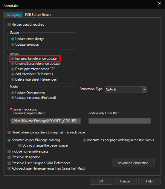
Step 7: Select the option for Incremental Reference Update under Action to update only components with question marks at the end.
Note: The following annotation actions are available from this menu:
- Incremental Reference Update: Updates any unfilled references in the design.
- Unconditional Reference Update: Updates all references in the design regardless of status.
- Reset Part References to ‘?’: Changes all part references to question marks.
- Add Intersheet References: Creates intersheet references between multiple pages in the schematic as required.
- Delete Intersheet References: Deletes all intersheet references.
Step 8: Under Mode, select Update Instances.
Note: Select Update Occurrences if annotating a hierarchical design. Each occurrence of a part will be given a separate reference designator.
Configuring Advanced Annotation Settings (Optional)
Note: The following annotation settings are optional. To start annotation from the Annotate window, click OK.
Step 9: Select Advanced Annotation to open the Advanced Annotation panel.
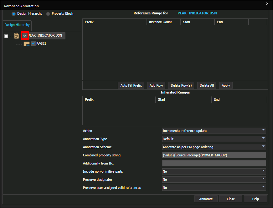
Step 10: The Advanced Annotation settings panel opens. Here you can configure the desired range for each prefix and other advanced annotation settings. Check PEAK_INDICATOR.dsn under Design Hierarchy.
Note: This will enable the annotation algorithm to be run on the design file. For design files with multiple pages, pages can be filtered from here as well.
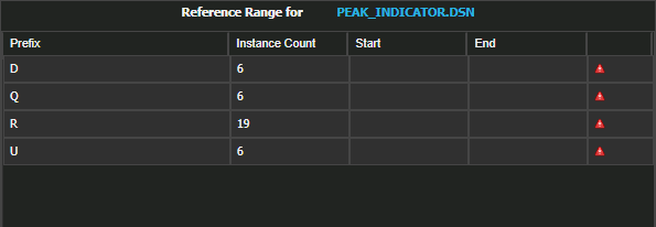
Step 11: Select Auto Fill Prefix. The reference table is filled and a count for each prefix is shown. Start and end reference designators can be defined in this table, for example, if conventions require the first component number to be 100 or 1000.
Step 12: Select Top-Bottom from the Annotation Type dropdown.
Note: This will annotate components from top to bottom first.
Automatically Assign Reference Designators
Step 13: Click Annotate to run the annotation.
Step 14: A prompt appears with the message that the design will be saved after it is annotated. Click OK to proceed.
Step 15: View the schematic. All components are annotated and none of the reference designators contain question marks.
Wrap Up & Next Steps
Automatically assign reference designators to your design with annotation and advanced annotation in OrCAD X Capture to save time and ensure components and design intent are accurately communicated in the PCB design process. Test out this feature and more with a free trial of OrCAD X. Want to learn more about Capture? Get access to free how-tos, courses, and walk-throughs at EMA Academy.

