AI tools can be used to accelerate the PCB design process, but designers must configure settings to get the most out of the results. X AI is integrated directly into your OrCAD X PCB canvas, outlining the requirements and ensuring designers configure settings for X AI that provide the correct inputs.
This quick how-to will provide step-by-step instructions on how to configure settings for Allegro X AI to achieve accurate copper pouring or component placement in OrCAD X.
To follow along, download the provided files above the table of contents.
How-To Video
 Open in New Window
Create an X AI Workspace
Step 1: Open the provided design in OrCAD X.
Step 2: Configure settings for X AI in the X AI settings panel. To open the panel, select Tools > X AI from the menu.
Step 3: Select Login and enter your Cadence username and password.
Step 4: Select Create New Workspace at the top of the Workspaces panel.
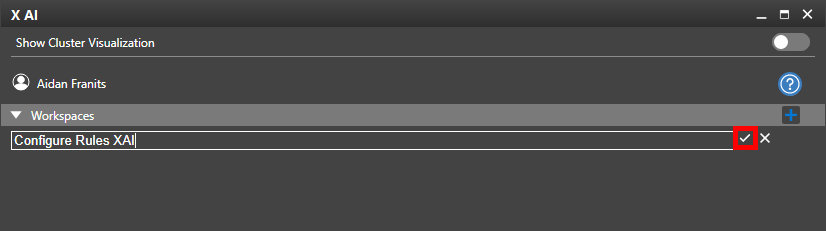
Step 5: Enter a name for the new workspace and click the checkmark button to create it.
Step 6: In the main workspace window, select Upload Board to upload the currently-loaded board to the X AI server.
Configure Settings for X AI: Components
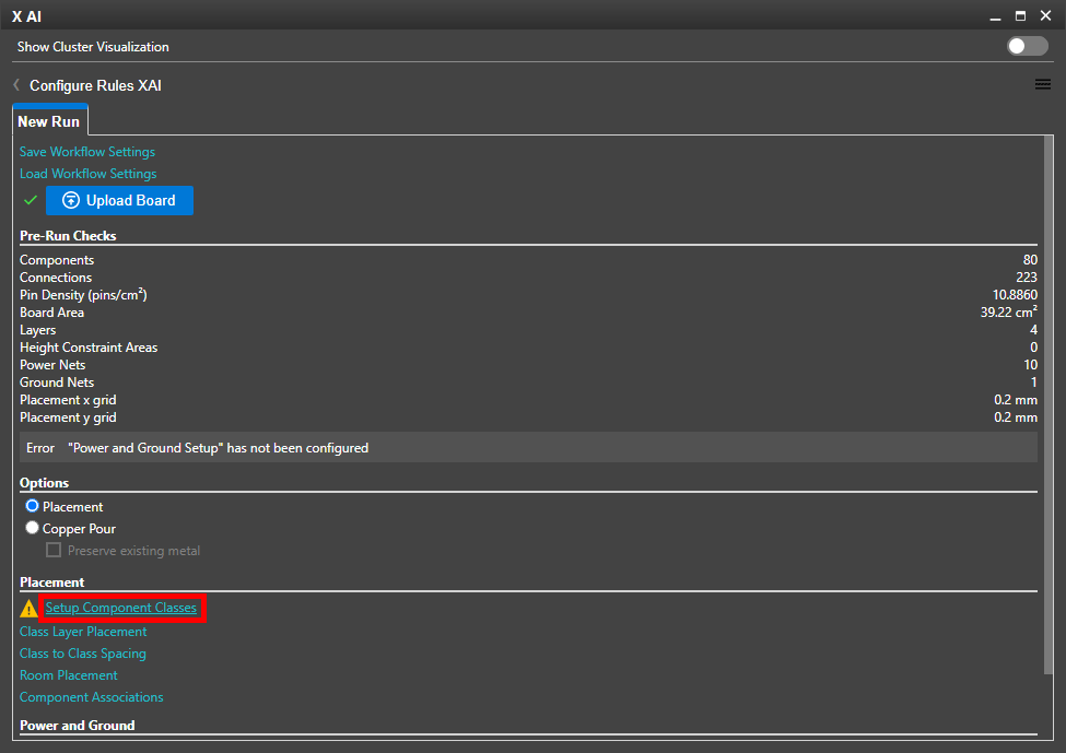
Step 7: Before running the placement or copper pour procedure, ensure component classes and power/ground layers are configured properly. Placement settings become available in the X AI panel.
Select Setup Component Classes to define unassigned component classes.
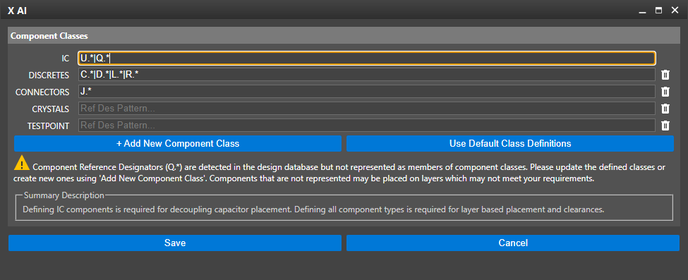
Step 8: The Component Classes list opens, indicating that reference designator Q.* is present on the board but not assigned to any class. Add |Q.* to the IC field.
Note: The | symbol acts as a logical separator and the .* indicates a wildcard.
The entry Q.* will classify all components whose reference designators start with Q as ICs, even if followed by another letter.
To separate single-letter reference designators, format the relevant entries as X[0-9]+, where X is the desired reference designator.
Step 9: Click Save to save the changes and return to the main XAI window.
Step 10: Select Class Layer Placement to configure class layer placement rules.
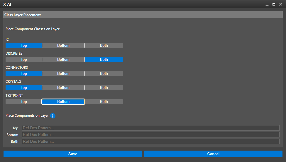
Step 11: The Place Component Classes on Layer subpanel opens. Here you can configure which component classes are allowed on the top, bottom, or both layers. Choose the following class layer settings:
- IC: Top
- Discretes: Both
- Connectors: Top
- Crystals: Top
- Testpoint: Bottom
Step 12: Click Save to save the settings and return to the main XAI window.
Configure Settings for X AI: Spacing
Step 13: Select Class to Class Spacing in the X AI window to configure component spacing settings.
Step 14: In the Class to Class Spacing table, enter 0.254 for the default clearance.
Step 15: Select Autofill Classes. All spacing pairs are listed in the table.
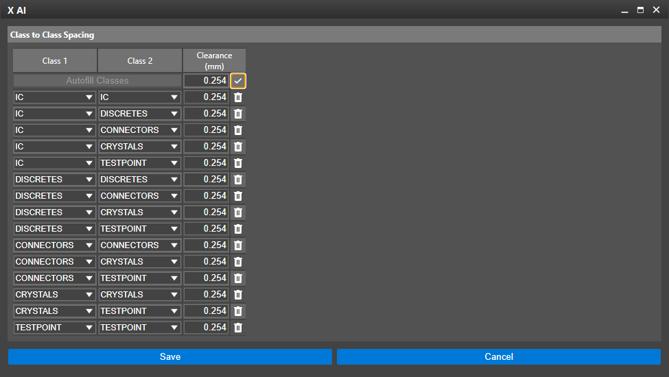
Step 16: Select Apply Default Clearance to apply the defined default clearanceto each spacing pair.
Step 17: Click Save to save the settings and return to the main X AI window.
Configure Settings for X AI: Room Placement Rules
Step 18: Select Room Placement in the X AI window.
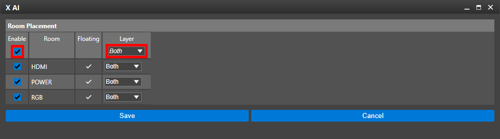
Step 19: In the Room Placement table, check the option for Enable for all rooms.
Step 20: Select Both under Layer for all rooms.
Note: Uncheck the option for Enable to ignore room placement.
Step 21: Click Save to save the settings and return to the main X AI window.
Configure Settings for X AI: Power and Ground
Step 22: Lastly, before any X AI operation is run, the power and ground placement rules must be defined. Select Power and Ground Setup.
Step 23: The Power and Ground Setup table opens. For this design, power and ground net voltages have already been assigned and are listed in the Voltage row.
A prompt is shown, saying that power and ground settings were pre-populated from the design. Click OK to close the prompt.
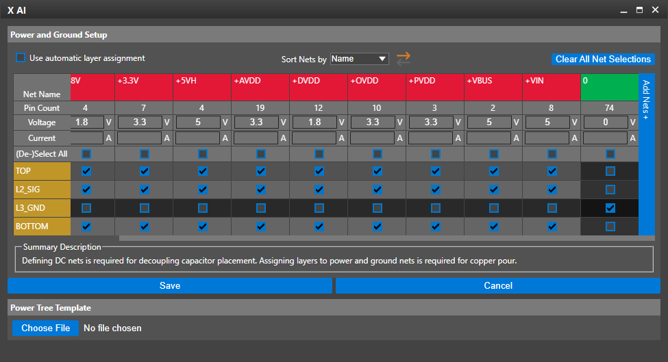
Step 24: Check the options for all layers except L3_GND for all power nets, indicated in red. Check the option for L3_GND for the ground net.
Step 25: Click Save to save the settings and return to the main X AI window.
The X AI placement or pour is ready to be run.
Note: All X AI settings are automatically saved in the selected workspace.
Wrap Up & Next Steps
Quickly and easily configure settings for X AI including spacing, room, and component class rules to ensure AI will return results that meet your design and functionality criteria with X AI in OrCAD X. Learn more about X AI here and get more how-tos for OrCAD X at EMA Academy.

