

When selecting components for a PCB design, it’s important that designers have concise, accurate, and comprehensive data available to review. With Component Information Portal (CIP), you can easily configure tables to customize views, filter out irrelevant information, prioritize critical information, and arrange how database information is displayed.
This quick how-to will provide step-by-step instructions on how to configure tables in CIP to customize views and enable designers to make informed part decisions upfront.
How-To Video
 Open in New Window
Viewing Your Component Database
Step 1: Select CIP > Open CIP from the menu.
Step 2: To preview the affected part before it is changed, expand and select Search > CIS Database from the CIP sidebar menu.
Step 3: A blank search opens. Select Manufacturer PN from the Parametric Field dropdown.
Step 4: Select Contains from the Operator dropdown.

Step 5: Enter MAX1953 for the Parameter. Click Search to run the search.
Step 6: A list of parts opens at the bottom of the panel. Select one of the part numbers to view the part properties.
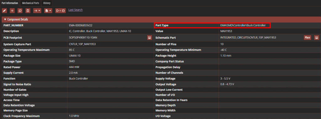
Step 7: View the table of properties. The part type is shown as EMA\SMD\Controller\Buck Controller and is labeled as Part Type.
Configure Tables in CIP: Consolidating Component Views
By default, all properties for a specific part type or view are shown, even if they are not defined for or applicable to that particular part. To make the table easier to read, unused rows can be removed from the component view.
Step 8: In the CIP menu sidebar, expand and select Admin > Configuration > Customizable Fields.
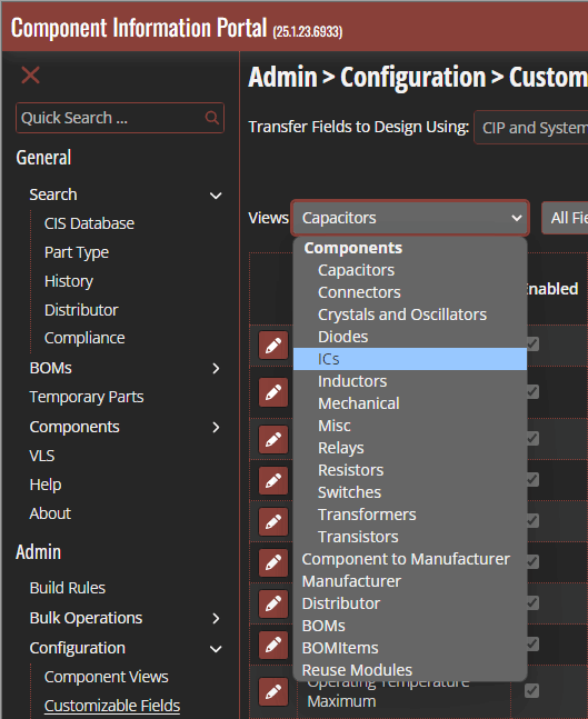
Step 9: The Customizable Fields table opens, showing all customizable fields for the selected view. To change the table for a different type of component, select it from the Views dropdown. For this example, select ICs.
Step 10: To edit a field, select the pencil icon. Unused fields can be used by disabling them in this view. Select the pencil icon for Signal to Noise Ratio.
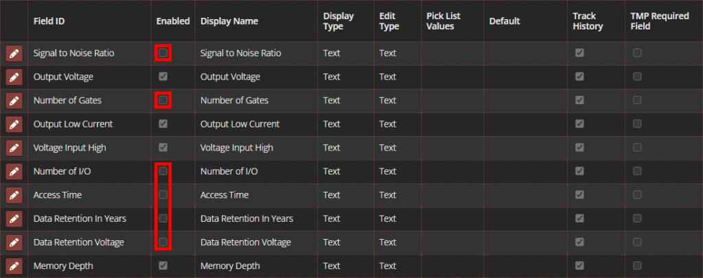
Step 11: Uncheck the option for Enabled to remove the field from the table.
Step 12: Click the checkmark to save the changes.
Note: Select Save All to apply the change to all views.
Step 13: Repeat steps 10-12 for the following fields:
- Number of Gates
- Number of I/O
- Access Time
- Data Retention in Years
- Data Retention Voltage
Configure Tables in CIP: Part Parameters
The names of fields provided in CIP can be changed to better suit company standards or conventions.
Step 14: Select the Edit buttonfor Part Type to edit the Part Type row.

Step 15: Under Display Name, change the display name to Category.
Note: For each parameter, you can also customize the type of form to display in normal or edit mode, the default value, where the parameter is required, and more.
Step 16: Click the checkmark to save the settings and close the edit mode.
Viewing Customized Tables
Step 17: To search for a part to test the new Part Type cells, in the CIP menu sidebar, expand and select Search > CIS Database.
Step 18: A blank search opens. Select Manufacturer PN from the Parametric Field dropdown.
Step 19: Select Contains from the Operator dropdown.
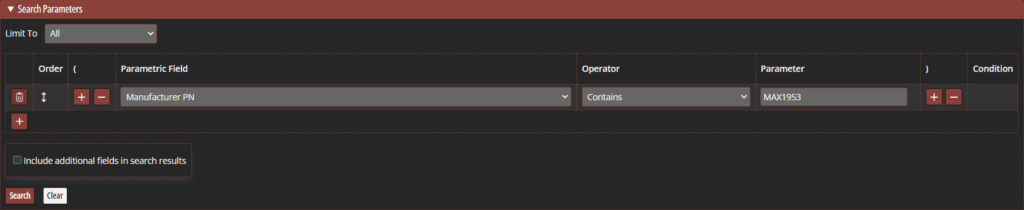
Step 20: Enter MAX1953 for the Parameter. Click Search to run the search.

Step 21: A list of parts opens at the bottom of the panel. Select one of the part numbers to view the part properties.
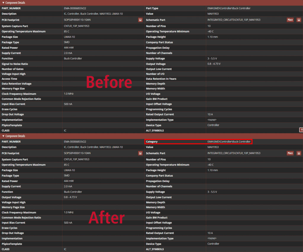
Step 22: View the part details. The category (part type) is listed as EMA\SMD\Controller\Buck Controller. The field title of “category” indicates that the change was successful. Additionally, the inapplicable properties such as data retention are no longer shown.
Configure Tables in CIP: Creating Custom Fields
Additional fields can be added to CIP views as needed to communicate part cost, availability, company preference, and more.
Step 23: Custom parameters can be mapped and displayed in a component detail table. Select Admin > Configuration > Customizable Fields from the CIP Sidebar Menu.
Step 24: Select ICs from the Views dropdown.
Step 25: Scroll to the user fields.
Step 26: Select the pencil for UserField01 to edit it.
Step 27: Check the option for Enable to enable the field.
Step 28: Enter Mounting Type for the Display Name.

Step 29: Enter Surface Mount for the Default Value.
Step 30: Check the option to Transfer to Design to transfer the property when the part is placed in the design.
Step 31: Select the checkmark to save the field and exit edit mode.
Viewing Custom Fields
Step 32: To preview the new field, select Search > CIS Database from the CIP sidebar menu.
Step 33: Under Search Parameters, set the Parametric Field to Manufacturer PN, the Operator to Contains, and the Parameter to MAX1953.
Step 34: Select Search and choose a matching component.
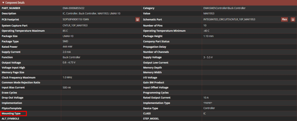
Step 35: Scroll to the bottom of the table. A blank cell labeled Mounting Type is shown.
Configure Tables in CIP: Rearranging a Table
By default, view tables in the CIP database have a fairly consistent arrangement. For certain types of parts, this may require scrolling to view the most relevant data. Table fields can be rearranged to prioritize the relevant properties for each view.
Step 36: To rearrange field positions in a table, select Admin > Configuration > Reorder View Fields from the CIP sidebar menu.
Step 37: Select ICs from the Views dropdown.
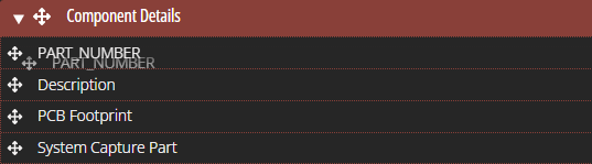
Step 38: Click and drag a field in the Component Details table to change how it will be displayed in the component view.
Step 39: Click the checkmark by the Views dropdown to save the changes.
Configure Tables in CIP: Creating a New View
Step 40: New views can be created through the Component Views window and table. To open this table, select Admin > Configuration > Component Views from the menu.
Step 41: The Component Views table opens. Here you can enable, disable, and configure additional views for each view set in CIP. Select the pencil icon for CIP_Capacitors to edit the view. A wider cell opens in the View Names column.

Step 42: Enter Polarized Capacitors for the view name and click the plus sign to add the view.
Step 43: Click the checkmark to save the changes. A view labeled “Polarized Capacitors” is added to the list.
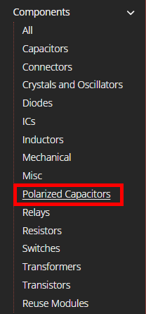
Step 44: Expand the Components list in the CIP menu sidebar. Polarized Capacitors is listed as its own component type.
Step 45: To remove the view, select the pencil icon for CIP_Capacitors again.
Step 46: Select Delete View for Polarized Capacitors.
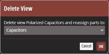
Step 47: A prompt appears with a dropdown, asking where to reassign parts from the view. Select Capacitors and click OK. The view is shown with a strikethrough.
Step 48: Click the checkmark. The view is removed.
Wrap Up & Next Steps
Quickly and easily configure tables in CIP to improve visibility and clarity of database information and streamline part selection and management. Get more step-by-step instructions for CIP at EMA Academy.

