

With today’s designs increasing in complexity, keeping a schematic organized and readable is important Keeping a schematic organized and readable is important to clearly communicate design intent and prevent errors throughout the PCB design process. Block diagrams can be used to visualize the design and provide a high-level overview of functionality. Easily create a block diagram and hierarchical block diagrams directly in the schematic canvas with OrCAD X Capture.
This quick how-to will provide step-by-step instructions on how to create a block diagram with shapes in OrCAD X Capture.
To follow along, download the provided files above the table of contents.
How-To Video
 Open in New Window
Create a Block Diagram in OrCAD X Capture
Step 1: Open the provided HDMI_DAC.dsn in OrCAD X Capture.
Note: For this example, we will make a block diagram from an existing design where the connections are known.
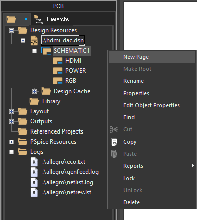
Step 2: Right-click SCHEMATIC1 in the Project Manager and select New Page to create a new page.
Step 3: The New Page window opens. Enter BLOCK DIAGRAM for the name and click OK.
Step 4: The new page is added to the Project Manager. Double-click the page to open it.
Step 5: First, a title must be added to the top of the page. Select Place > Text from the menu.
Step 6: The Place Text window opens. Here you can define the text to display and its properties. Select Change under Font to change the font size.
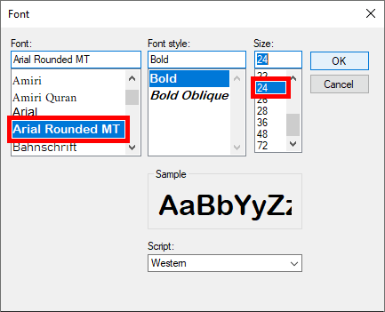
Step 7: The Font window opens. Select Arial Rounded MT from the Font list and 24 for the Size. Click OK to set the font.
Step 8: Back in the Place Text window, enter Block Diagram into the Text field and click OK to place the text.
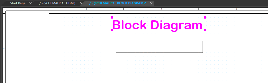
Step 9: Click to place the text near the top of the new page. Right-click and select End Mode.
Create a Block Diagram Manually: Placing the Blocks
Step 10: For this example, we will place a total of three blocks, one for each existing page. To place a block, select Place > Rectangle from the menu.
Step 11: Click to start drawing a rectangle in the canvas and click again to finish.
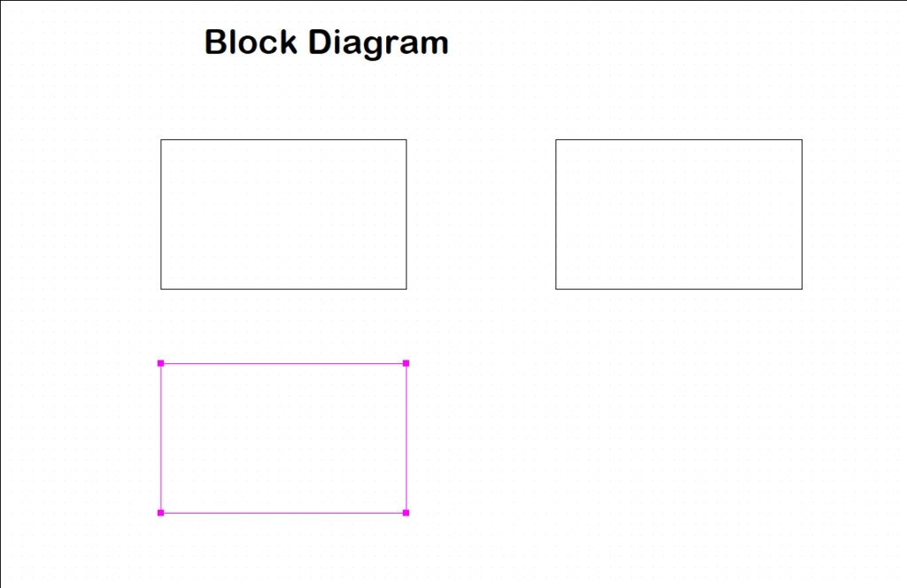
Step 12: Click to draw two more rectangles to the right of and below the first one. When finished, right-click and select End Mode.
Step 13: Having different colors in a block diagram will help distinguish each block. Double-click the first-drawn block to change its color.
Step 14: The Edit Filled Graphic window opens. Select Solid from the Fill Style dropdown.
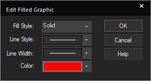
Step 15: Select the desired color from the Color dropdown at the bottom of the window.
Step 16: Click OK. The block color is set.
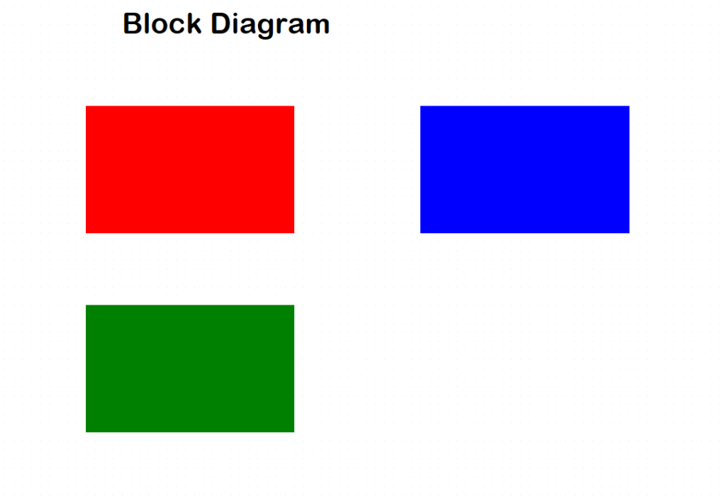
Step 17: Repeat steps 13-16 for the other blocks. The block colors are configured.
Create a Block Diagram: Adding Labels
Step 18: To name the blocks, select Place > Text again from the menu.
Step 19: Select Change under Font. Set the font size to 14 and click OK.
Step 20: Enter Power and Input for the text and click OK to place.
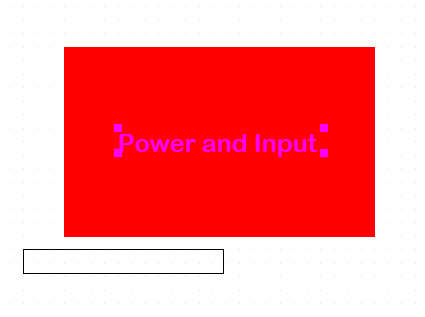
Step 21: Click OK and click again place the text within the first block.
Step 22: Press T on the keyboard to reopen the Edit Text window.
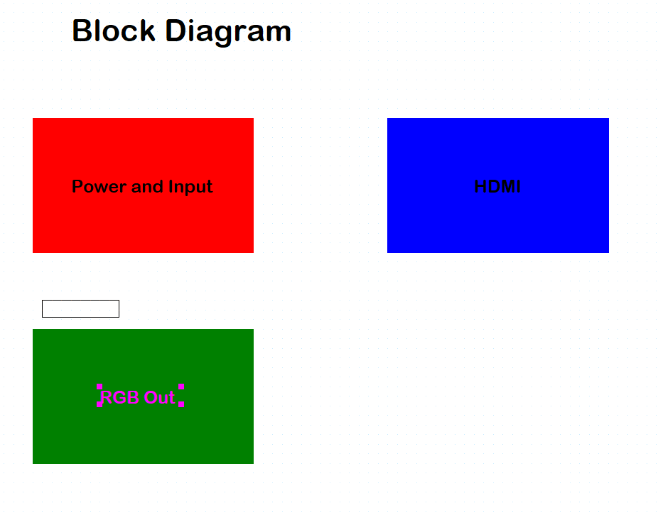
Step 23: Repeat steps 20-22 for blocks labeled HDMI and RGB Out. When finished, right-click and select End Mode.
Create a Block Diagram: Arrows and Nets
Step 24: To start drawing a block arrow, select Place > Line from the menu.
Step 25: Click to start drawing a line from the left edge of the Power and Input block and click again to finish outside the block.
Note: This arrow will be used to indicate external power input.
Step 26: To create the arrowhead, select Place > Polyline from the menu.
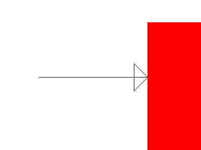
Step 27: Click to start drawing the line at the start of where the arrowhead should be. Click each point to create the arrowhead. The shape will be placed automatically when finished.
Note: Hold Shift on the keyboard to draw a diagonal line.
Step 28: Right-click and select End Mode.
Step 29: Double-click the arrowhead to add a fill.
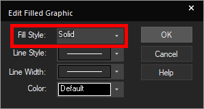
Step 30: The Edit Filled Graphics window opens. Select Solid for the fill style. Leave the color as default and click OK.
Step 31: To annotate the arrow, select Place > Text from the menu.
Step 32: The Place Text window opens. Select Change under Font.
Step 33: Set the font to Arial and the size to 10. Click OK.
Step 34: Enter USB +5V for the text and click OK.
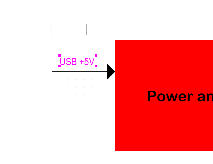
Step 35: Click to place the text above the arrow. Right-click and select End Mode.
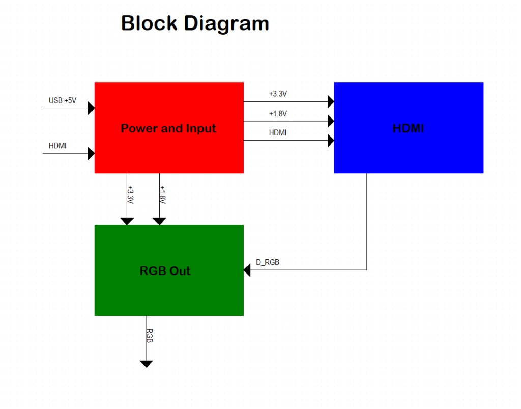
Step 36: Repeat steps 26-35 to place the arrows shown above.
Note: To duplicate an arrow, click and drag to select its components, then right-click and select Copy, and right-click and select Paste in the canvas. Click to place the arrow. Double-click the text to edit as needed.
Step 37: To save the design, select the hdmi_dac.dsn file in the Project Hierarchy. Select File > Save from the menu.
Wrap Up & Next Steps
Quickly create a block diagram to ensure your complex schematic remains easy to follow with OrCAD X Capture. Test out this feature and more with a free trial of OrCAD X. Want to learn more about Capture? Get access to free how-tos, courses, and walk-throughs at EMA Academy.

