

With today’s designs increasing in complexity, keeping a schematic organized and readable is important to prevent errors in the PCB design and test process. This is especially important when creating a complex or hierarchical schematic. Hierarchical block diagrams can be used to not only visualize the design and ensure all connections are intact, but also navigate the schematic at the click of a button and partition each functional region for better readability. Easily create a hierarchical block diagram directly in the schematic canvas with OrCAD X Capture.
This quick how-to will provide step-by-step instructions on how to create a block diagram with hierarchical blocks in OrCAD X Capture.
To follow along, download the provided files above the table of contents.
Note: To learn how to create a standard block diagram, see our how-to here.
How-To Video
 Open in New Window
Create a Hierarchical Block Diagram
A block diagram created from hierarchical blocks and ports will allow for navigation throughout the design while communicating the system-level design.
Step 1: Open the provided HDMI_DAC_Hierarchical.dsn in OrCAD X Capture. This design has been pre-configured with hierarchical ports. To learn how to create a hierarchical schematic view our how-to here.
Step 2: Right-click the design file in the Project Manager and select New Schematic.
Step 3: The New Schematic window opens. Enter Top for the name and click OK.
Step 4: Right-click the new schematic and select New Page. Enter BLOCK DIAGRAM for the name and click OK.
Step 5: Right-click the TOP schematic and select Make Root to assign the new schematic as the root schematic.
Note: The design must be saved before the root can be changed. When prompted, click Save Design to save the design.
Create Hierarchical Blocks
Step 6: Double-click the BLOCK DIAGRAM page under Top to open the new page.
Step 7: To place a hierarchical block, select Place > Hierarchical Block from the menu.
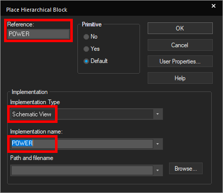
Step 8: The Place Hierarchical Block window opens. Select Default for the Primitive mode and enter POWER for the reference.
Note: For this example, hierarchical ports have already been placed. To learn more about how to create a hierarchical design, see our how-to here.
Step 9: Under Implementation, select Schematic View for the Implementation type. Select POWER for the Implementation Name.
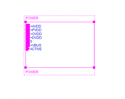
Step 10: Click OK. Click in the schematic canvas to start drawing the block and click again to finish. The POWER block is added.
Step 11: Select Place > Hierarchical Block again to place another block.
Step 12: Enter HDMI for the block reference. Select Schematic View for the Implementation Type and HDMI for the Implementation Name.
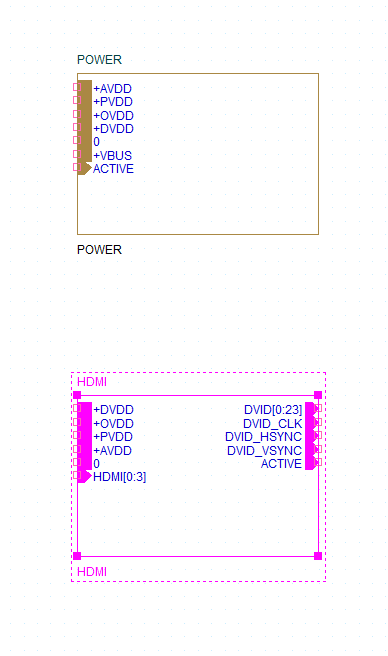
Step 13: Click OK. Click to start drawing the HDMI block and click again to finish.
Step 14: Select Place > Hierarchical Block again to place another block.
Step 15: Enter RGB for the block reference. Select Schematic View for the Implementation Type and RGB for the Implementation Name.
Step 16: Click OK. Click to start drawing the RGB block and click again to finish.
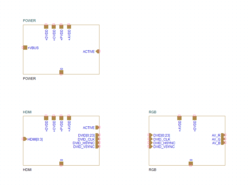
Step 17: Click and drag to adjust the hierarchical ports in the blocks to arrange them as shown above.
Placing Power and Ground
Step 18: Hierarchical blocks can be connected with the same power and ground symbols used in a schematic. To place the grounds, select Place > Ground from the menu.
Step 19: The Place Ground window opens. Select 0/Capsym from the list and click OK.
Note: If this option is not listed in the Place Ground window, select Add Library. Browse to the default library location, C:\Cadence\SPB_[version]\tools\capture\library. Select capsym.olb and click Open.
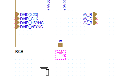
Step 20: Click to place a ground for each block. Right-click and select End Mode.
Step 21: To place power markers, select Place > Power from the menu.
Step 22: The Place Power window opens. Select VCC/Capsym from the list and click OK.
Step 23: Before placing, right-click and select Edit Properties.
Step 24: Enter +AVDD for the name and click OK.
Step 25: Click to place +AVDD markers at each block.
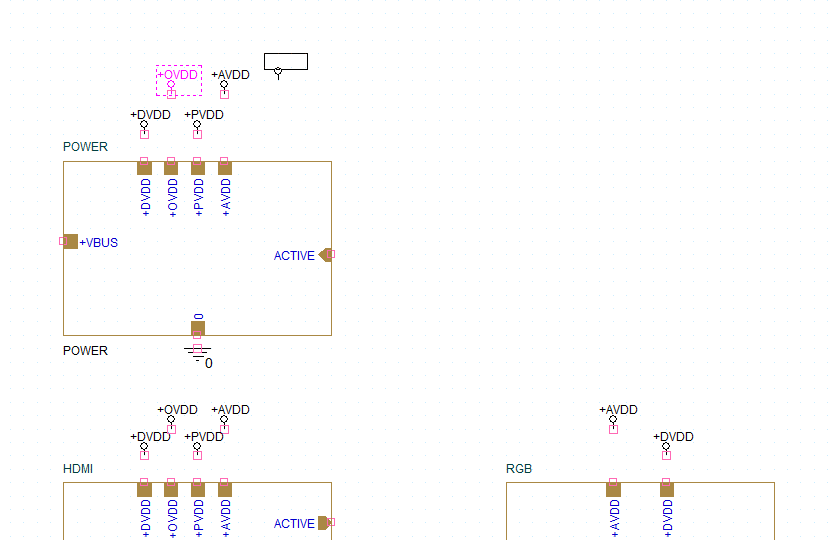
Step 26: Repeat steps 23-25 for +DVDD, +PVDD, and +OVDD. When finished, right-click and select End Mode.
Note: +PVDD and +OVDD do not connect to the RGB block.
Connecting the Blocks
Step 27: Hierarchical blocks can be connected with the same wires and buses used in their referenced schematics. Select Place > Wire from the menu.
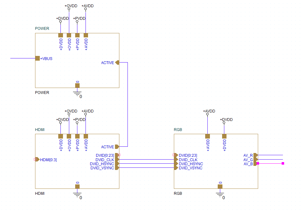
Step 28: Click to start drawing a wire and click again to finish. Wire the single-connection ports as shown.
Note: +VBUS, HDMI, and AV_R/G/B connect to components that have not been added to the block diagram yet.
Step 29: Select Place > Bus from the menu.
Step 30: Click to connect the DVID ports.
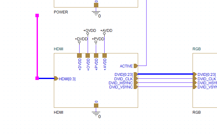
Step 31: Click to create a bus entry for the HDMI input port. Right-click and select End Mode.
Creating Inputs and Outputs
Step 32: Inputs and outputs can be added to a block diagram to make the design more readable. Expand the HDMI schematic in the Project Manager and double-click the HDMI page.
Step 33: The HDMI page opens. Click and drag to select connector J2 and its attached ground connections.
Step 34: Press CTRL-X on the keyboard to cut the connector.
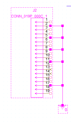
Step 35: Return to the BLOCK DIAGRAM page. Press CTRL-V to paste the connector. Click to place the connector to the left of the HDMI rail.
Step 36: Return to the HDMI page. Click and drag to select the HDMI connections, then press CTRL-C on the keyboard.
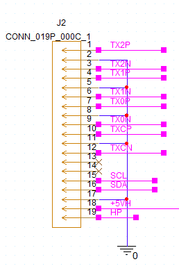
Step 37: Back in the BLOCK DIAGRAM page, press CTRL-V to paste the connections on the HDMI connector.
Step 38: Click and drag the open end of each wire to be one pixel away from the HDMI bus.
Step 39: To connect each wire to the bus, select Place > Bus Entry from the menu.
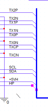
Step 40: Click to place the entries on the HDMI bus. Right-click and select End Mode when finished.
Note: Press R on the keyboard to rotate as needed.
Step 41: Expand the RGB schematic and double-click the page. Click and drag to select connector J3 and its associated ground. Press CTRL-X on the keyboard.
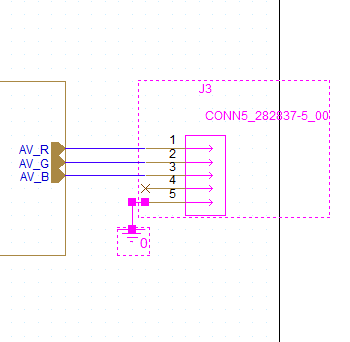
Step 42: Return to the BLOCK DIAGRAM page. Press CTRL-V to paste the connector at the AV_R/G/B outputs.
Step 43: Expand the POWER schematic and double-click the page. Click and drag to select connector J1 and its associated ground. Press CTRL-X on the keyboard.
Step 44: Return to the BLOCK DIAGRAM page. Press CTRL-V to paste the connector.
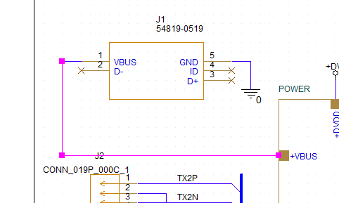
Step 45: Select Place > Wire from the menu. Click to connect Pin 1 of the USB connector to the +VBUS input of the POWER block. Press Escape on the keyboard when finished.
Labeling Nets
Step 46: The last step to create a hierarchical block diagram is to label the connections to ensure that the nets are connected. Select Place > Net Alias from the menu.
Step 47: The Place Net Alias window opens. Enter +VBUS for the net alias and click OK.
Step 48: The alias is attached to your cursor. Click to place the alias on the +VBUS net.
Step 49: Press N on the keyboard to reopen the Place Net Alias window.
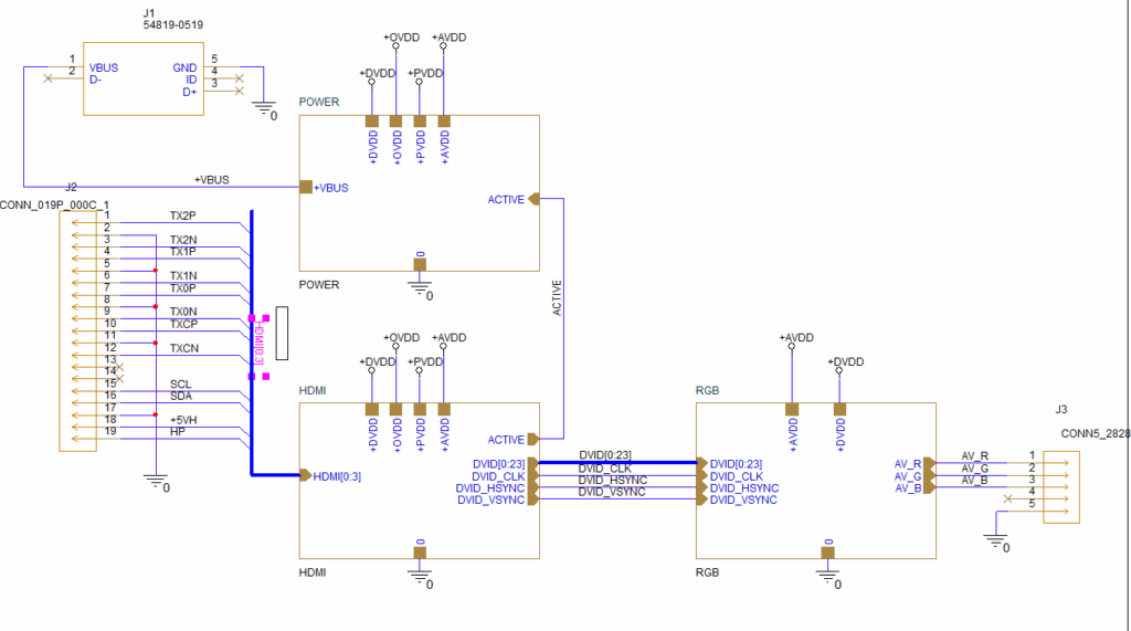
Step 50: Repeat steps 47-49 to place the aliases shown above.
Note: The power and ground markers and any pre-placed nets assign net aliases automatically. Blank nets can be aliased in any design with this procedure.
Annotate a bus with the bus name followed by [start:end] to indicate the net numbers contained within the bus.
Step 51: Select the design file in the Project Manager and select File > Save from the menu. The block diagram is created.
Wrap Up & Next Steps
Quickly create a hierarchical block diagram page to ensure your complex schematic remains easy to follow and navigable with OrCAD X Capture. Test out this feature and more with a free trial of OrCAD X. Want to learn more about Capture? Get access to free how-tos, courses, and walk-throughs at EMA Academy.

