With today’s designs and enclosures becoming more compact, board space and weight is at a premium for most new devices. PCB designers can create a cross-hatch plane, or a plane that uses a mesh or grid of copper instead of a solid copper fill, to:
- Improve flexibility in flex and rigid-flex
- Reduce copper weight and mass
- Improve impedance matching in flex circuits
- Improve adhesion during lamination
- Control EMI/EMC behavior in some RF applications
While cross-hatch planes have their trade-offs including poor return paths, higher inductance, and reduced shielding effectiveness, if a cross-hatch plane is beneficial for your design OrCAD X can help. With OrCAD X you can quickly and easily create a cross-hatch plane detailing the net, pattern, and specifications in OrCAD X Presto.
This quick how-to will provide step-by-step instructions on how to create a cross-hatch plane in OrCAD X Presto.
To follow along, download the provided files above the table of contents.
How-To Video
 Open in New Window
Create a Cross-Hatch Plane
Step 1: Open the provided Cross_Hatch_Board.brd design in OrCAD X Presto.
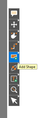
Step 2: To create a copper shape, select the Add Shape mode from the toolbar.
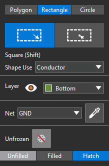
Step 3: The Add Shape widget opens. Here you can configure the type of shape to draw, its function and layer, and for copper shapes, its net. Select Rectangle.
Step 4: In the Add Shape widget, set the Shape Use to Conductor, the Layer to Bottom, and the net to GND.
Step 5: Select Hatch at the bottom of the widget to create a cross-hatch shape.
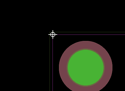
Step 6: Hover over the upper-left corner of the conductor/package keepin on the board. A crosshairs icon appears.
Note: This will snap the upper-left corner of the shape to the keepin corner so the copper retains the shape of the board.
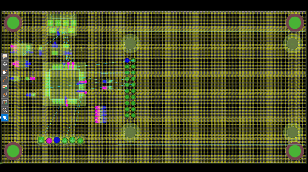
Step 7: Click to start drawing the shape and click the lower-right corner of the conductor/package keepin to finish. A shape with a cross-hatch fill is drawn.
Step 8: Choose the Select mode from the toolbar. The new shape remains selected.
Step 9: View the Shape Fill subpanel in the Properties panel. Options to configure the cross-hatch fill are shown.
Creating a Cross-Hatch Plane: Rigid-Flex Designs
Step 10: Cross-hatching can also be added to rigid flex designs to ensure that flex zones remain flexible. Open the provided Cross_Hatch_Flex.brd design in OrCAD X Presto.
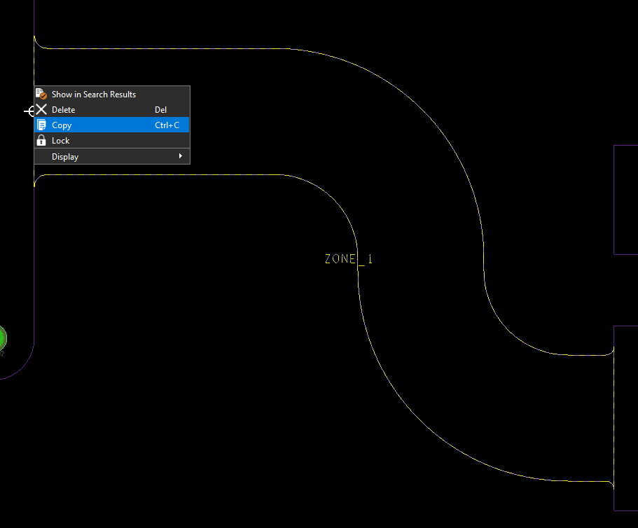
Step 11: In a rigid-flex design, to retain the geometry, the zone outline can be copied to a copper plane. Select the outline for Zone_1, right-click and select Copy.
Step 12: Right-click and select Paste Special.
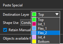
Step 13: A copy of the zone outline is attached to your cursor and the Paste Special widget opens. Conductor is already selected as the shape type. Select Flex_2 as the destination layer.
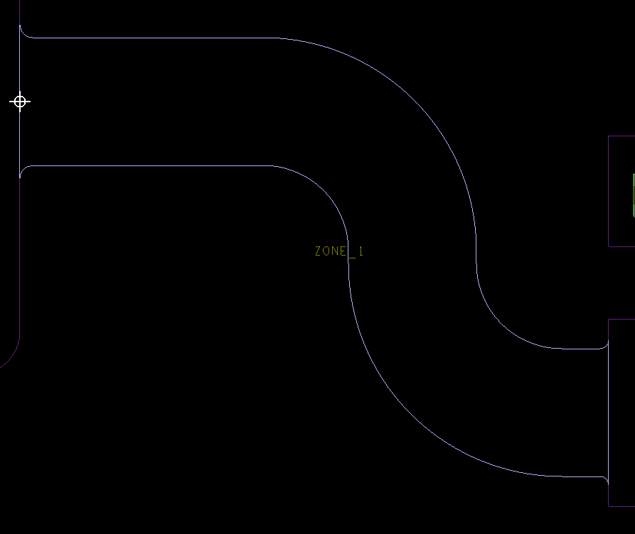
Step 14: Move the mouse until the Flex_2 shape attached to the cursor is centered over the flex outline and click to place.
Step 15: Click the Select mode from the toolbar to end placement.
Adjusting the Plane
Step 16: Since the plane was generated as a copy of the zone geometry, the plane extends beyond its conductor keepin zones. To fix this, select the plane.
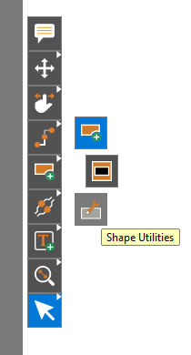
Step 17: Right-click the Add Shape mode in the toolbar and select Shape Utilities.
Step 18: The Shape Utilities widget opens. Select Resize and Contract.
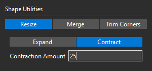
Step 19: Enter 25 for the Contraction Amount.
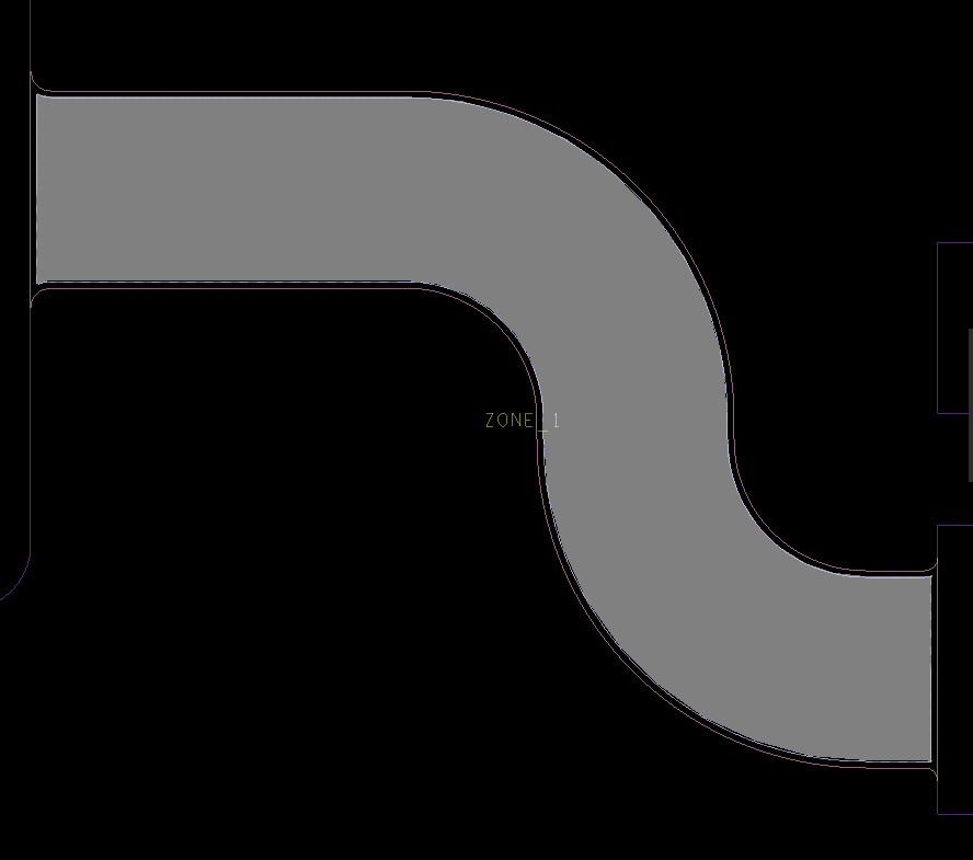
Step 20: Click the shape to contract it.
Step 21: Choose the Select mode from the toolbar.
Create a Cross-Hatch Plane
Step 22: By default, planes created with the Paste Special command are solid-filled. To change this, select the shape.
Note: Shape properties will appear in the Properties panel if it is selected.
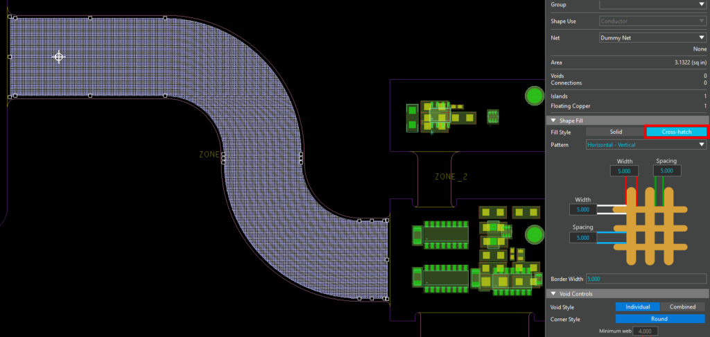
Step 23: Select Cross-Hatch under Shape Fill. Cross-hatching is added.
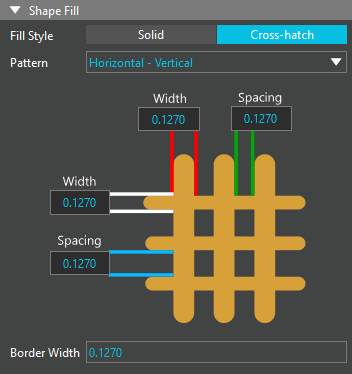
Step 24: Scroll down in the Properties panel so more of the Shape Fill subpanel is visible. Here you can configure the thickness, spacing, and direction of the cross-hatch.
Step 25: Select Diagonal Positive from the Pattern dropdown.
Note: The pictorial in the subpanel changes to match the selected pattern.
Step 26: Set the Width and Spacing to 25. The Border Width is adjusted automatically.
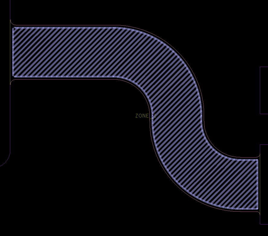
Step 27: Click anywhere in the schematic to deselect the shape. A cross-hatch plane has been added to the flex zone.
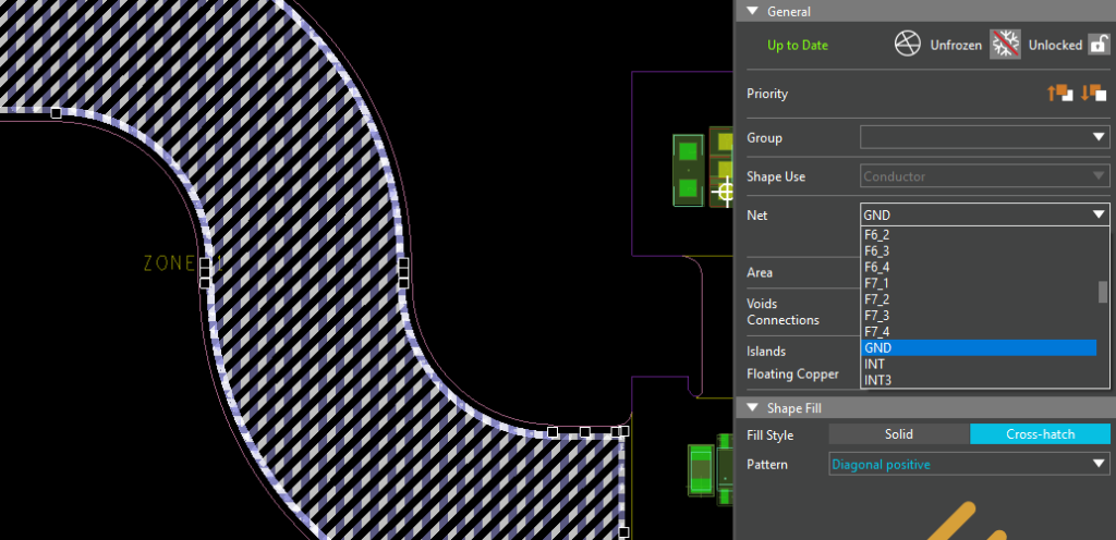
Step 28: A ground net can be assigned to this plane by selecting the shape in the canvas. Choose the desired net from the Net dropdown.
Wrap Up & Next Steps
Quickly and easily create a cross-hatch plane to reduce copper usage and ensure flexibility with OrCAD X. Test out this feature and more with a free trial of OrCAD. Get more how-tos for OrCAD at EMA Academy.

