A Custom workflow can have many benefits within your design process- from helping you remember all the necessary tasks for a successful design to creating consistency for multiple team members. With some simple coding and OrCAD’s ability for customization, you can create and utilize a custom workflow for any aspect of the design.
This how-to will provide step-by-step instructions on how to create a custom workflow in OrCAD PCB Designer.
Workflow Syntax
Below is the syntax for coding a workspace:
<?xml version=”1.0″ encoding=”utf-8″?>
<workspace version=”1.0″ name = “WORKSPACE NAME” defaultTool=”PCB”>
<workflow name=”WORKFLOW NAME“>
<task name=”TASK NAME” command=”COMMAND“></task>
<group name=”GROUP NAME“>
<task name=”TASK NAME” command=”COMMAND“></task>
<task name=”TASK NAME” command=”COMMAND; COMMAND“></task>
</group>
</workflow>
</workspace>
Note: The items in BOLD are the portions of the code that need to be changed by you. Your workspace can contain any combination of workflows, groups, and tasks. These aspects are all customizable based on your preference; however, the commands need to be derived from PCB Editor.
Glossary of Terms
WORKSPACE NAME
This is the name of the custom workflow and will need to be different than any existing workflow.
WORKFLOW NAME
This is an expandable section containing groups and tasks and can be used for organization within the workflow.
GROUP NAME
This is an expandable section containing tasks and can be used for organization within the workflow.
TASK NAME
This is the name of a task within the workflow.
COMMAND
This is the command associated with the task you would like to complete in PCB Editor. Multiple commands can be combined into one string to produce the desired action.
Creating a Workspace
Step 1: Open a blank text file (.txt)
Note: Within the text file the custom workflow is referred to as the workspace. A workspace consists of tasks which can be organized into groups and workflows.
Step 2: Define a workspace. Copy and paste the following into the text file:
<?xml version=”1.0″ encoding=”utf-8″?>
<workspace version=”1.0″ name = “WORKSPACE NAME” defaultTool=”PCB”>
</workspace>
Step 3: Replace the WORKSPACE NAME with the desired name of the workspace.
Creating a Workflow
Step 4: Copy and paste the following into the body of the workspace:
<workflow name=”WORKFLOW NAME“>
</workflow>
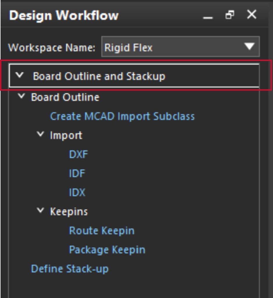
Step 5: Replace the WORKFLOW NAME with the desired name of the workflow.
Step 6: Add the desired combination of tasks and groups to the workflow.
Creating a Task
Step 7: Copy and paste the following in the body of the workflow:
<task name=”TASK NAME” command=”COMMAND“></task>
Step 8: Replace the TASK NAME with the desired name of the task.
Step 9: Replace the COMMAND with the command used in OrCAD PCB Designer.
Note: To determine the desired commands, use the following steps:
- Open PCB Editor.
- Select Display > Windows > Command from the menu.
- Type scriptmode +e in the command prompt. Click Enter.
- Execute the desired action in PCB Editor.
The code will be shown in the command window and can be copy/pasted into your text file.
Creating a Group
Step 10: Copy and paste the following into the body of the workflow:
<group name=”GROUP NAME“>
</group>
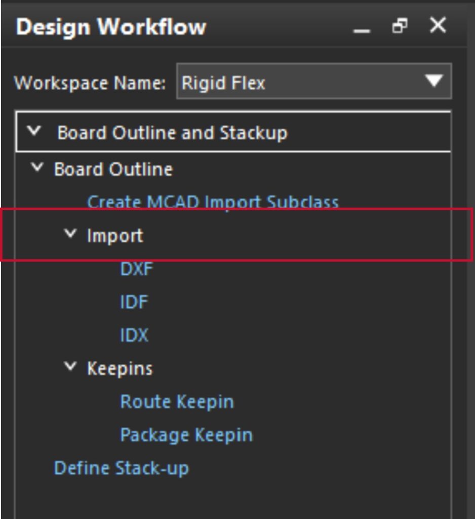
Step 11: Replace the GROUP NAME with the desired name for the group.
Step 12: In the body of the Group, add the desired tasks. Copy and paste the following:
<task name=”TASK NAME” command=”COMMAND“></task>
<task name=”TASK NAME” command=”COMMAND; COMMAND“></task>
Step 13: Replace the TASK NAME with the desired task name.
Step 14: Replace the COMMAND items with the corresponding commands in OrCAD PCB Designer.
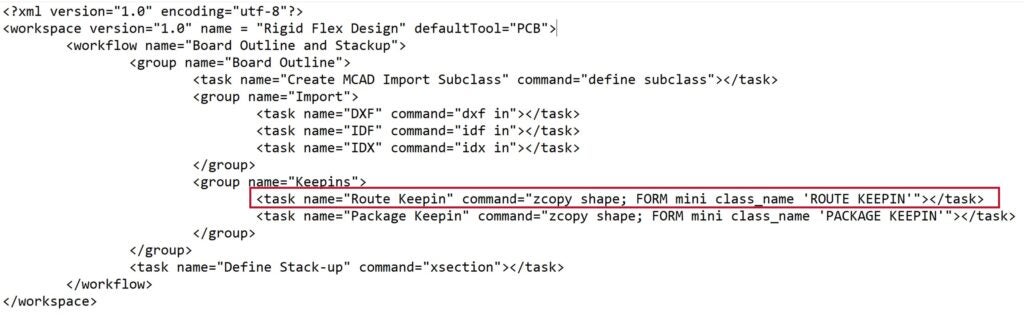
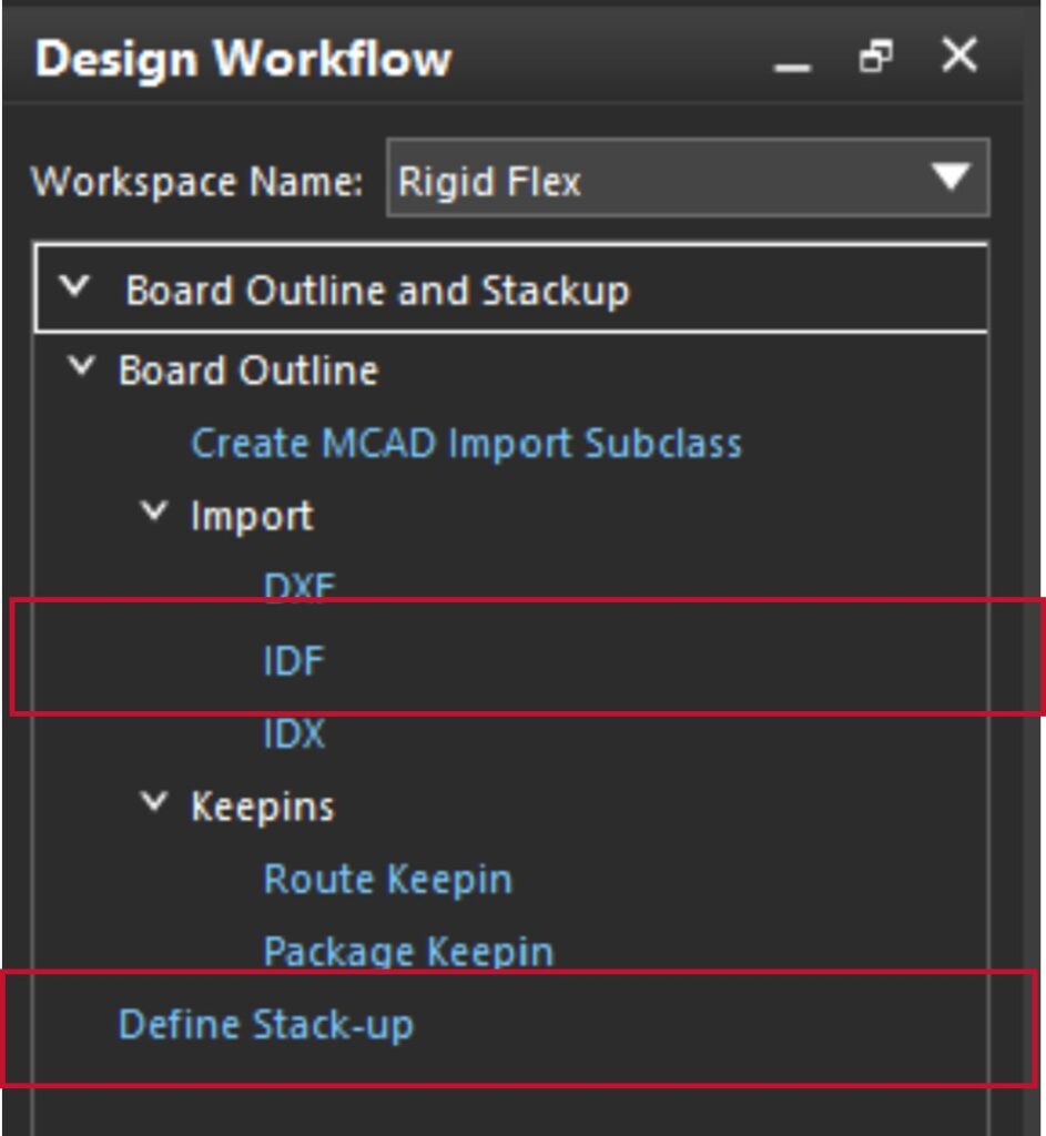
Note: If multiple commands need to be executed, separate the commands with a semicolon. For example, the code highlighted in red contains additional commands separated by a semicolon.
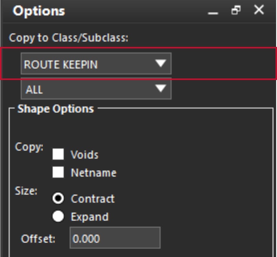
This code eliminates an extra step and allows you to automatically set the Active Class to Route Keepin in the Options Window.
Completing the Workspace
Step 15: Complete the workspace with the desired combination of workflows, groups, and tasks.
Note: Your workspace can contain any combination of workflows, groups, and tasks. These aspects are all customizable based on your preference; however, the commands need to be derived from PCB Editor.
Step 16: When the workflow is finished or you want to test out the custom workflow, save the file as a .XML.
Step 17: Copy and paste the file into the standard path for workflows: C:\Cadence\SPB_17.4\share\pcb\text\workflows
Step 18: Open OrCAD PCB Designer.
Step 19: Select Display > Windows > Design Workflows from the menu.
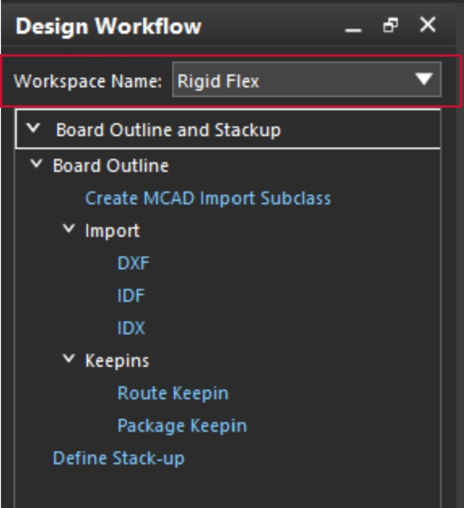
Step 20: Select your custom workflow from the Workspace drop-down menu.
Tips & Tricks for Creating Workflows
Here are some tips when completing this process:
- Remember to close out a section with </workspace>, </workflow>, </group>, or </task> accordingly.
- If you are copying/pasting multiple commands, remember to separate them with semicolons in your code.
- Change any double quotations to single quotations in copy and pasted code.
- Double check your code for spelling or syntax errors.
Wrap Up & Next Steps
The possibilities for custom workflows are endless and can be beneficial for both new and seasoned designers, creating consistency for your entire design team; however, this process can be time-consuming. To reap the benefits without putting in hours of coding, check out EMA’s EDA Store for free, pre-built workflows for Differential Pairs, Rigid-Flex Designs, Footprint Creation, and Manufacturing Preparation.

