With today’s designs increasing in complexity, keeping a schematic organized and readable is important to prevent errors in the PCB design and test process. In cases where a design can be divided into functional regions, hierarchical blocks can be used to partition the major functional regions of a design using a block symbol, a part with an attached schematic page or model. OrCAD X Capture makes it easy to create a hierarchical schematic using hierarchical blocks with references, ensuring that the design remains organized as it becomes more complex.
This quick how-to will provide step-by-step instructions on how to create and configure a hierarchical schematic in OrCAD X Capture.
To follow along, download the provided files above the table of contents.
How-To Video
 Open in New Window
Create a Hierarchical Schematic
Step 1: Open the provided project in OrCAD X Capture. For this example, the existing design will be converted into a lower hierarchy.
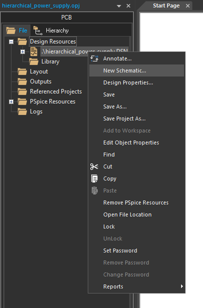
Step 2: In the Project Manager, right-click the design file and select New Schematic.
Step 3: The New Schematic window opens. Leave the default SCHEMATIC1 as the name and click OK.
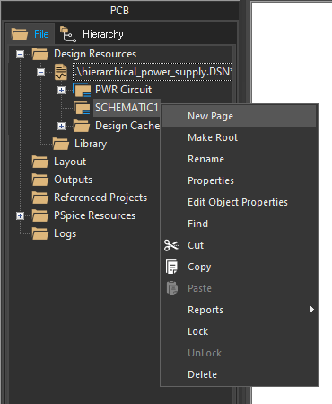
Step 4: In the Project Manager, the design file expands to show the existing PWR Circuit schematic and the new schematic. Right-click the new schematic and select New Page.
Step 5: The New Page window opens. Leave the default PAGE1 as the name and click OK.
Step 6: Right-click SCHEMATIC1 in the project hierarchy and select Make Root to assign the new, empty schematic as the root schematic.
Note: The design must be saved before the root can be changed. When prompted, click Save Design to save the design.
Create a Hierarchical Schematic: Input Ports
Step 7: Before a schematic can be used in a hierarchical block, hierarchical ports must be added. Double-click PAGE1 under PWR Circuit to open the power supply circuit.
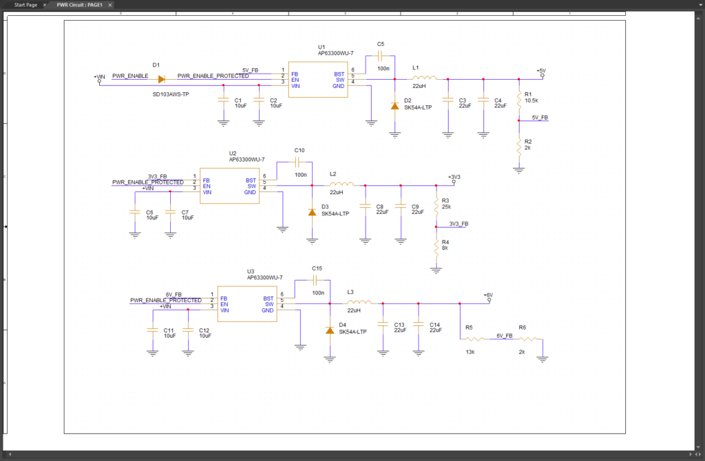
The power supply circuit opens in the schematic canvas.
Step 8: Hold CTRL on the keyboard and select the markers for +VIN, +5V, +3V3, and +6V. Press Delete on the keyboard to remove the markers.
Step 9: Select the PWR_ENABLE net alias in the top left of the schematic and press Delete on the keyboard.
Step 10: Hierarchical ports will automatically assign net aliases. Select Place > Hierarchical Port from the menu.
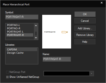
Step 11: The Place Hierarchical Port window opens, listing all available hierarchical ports. Scroll down and select PORTRIGHT-R from the port list and click OK to place an input port.
Note: Other hierarchical ports can be placed from this window, including:
- PortLeft-L/R: Output port. The L/R suffix determines the port’s initial orientation.
- PortBoth-L/R: Bidirectional port.
- PortNo-L/R: Passive port.
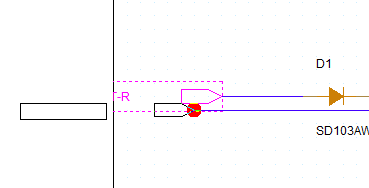
Step 12: Click to place input ports on the former +VIN and PWR_ENABLE nets. Right-click and select End Mode when finished.
Note: Press R on the keyboard to rotate the ports as needed.
Step 13: Click and drag to adjust the ports so they are stacked.
Step 14: Double-click the name of the top port to change it. In the Display Properties window, enter PWR_ENABLE and click OK.
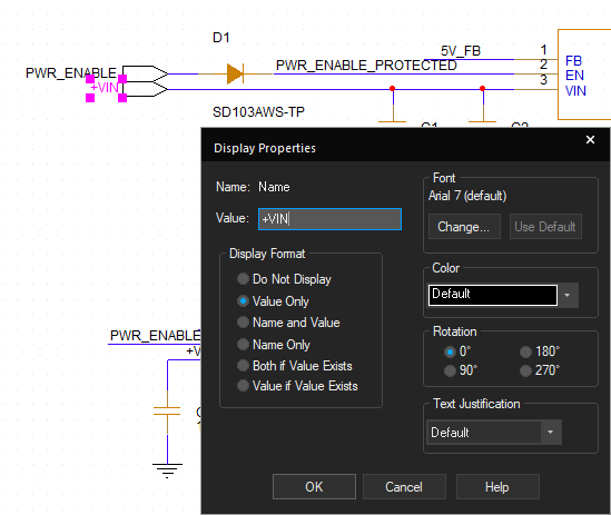
Step 15: Double-click the name of the bottom port. In the Display Properties window, enter +VIN and click OK. This will re-assign the removed net aliases. Because the +VIN alias is still assigned on U2 and U3, those wires are now connected to the input port.
Create a Hierarchical Schematic: Output Ports
Step 16: Select Place > Hierarchical Port from the menu.
Step 17: Select PORTLEFT-R from the list and click OK to place an output port.
Step 18: Click to place output ports at the output of each voltage regulator. Right-click and select End Mode.
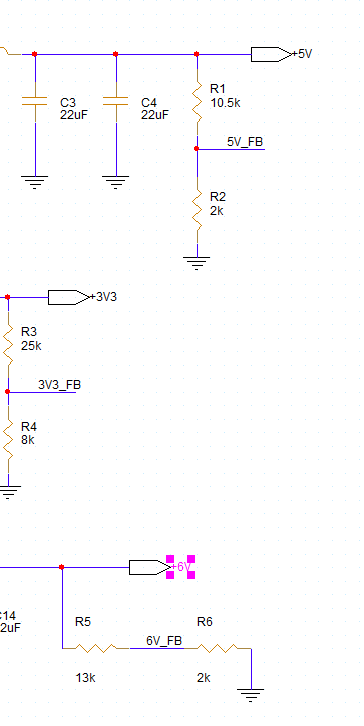
Step 19: Double-click the name of each output port and change the name of the top, middle, and bottom ports to +5V, +3V3, and +6V, respectively. Click OK in each resulting window.
Step 20: Select the DSN file in the Project Manager and select File > Save from the menu to save the schematic. Click Yes to All to save all pages when prompted.
Close the schematic page tab.
Place a Hierarchical Block
Step 21: In the Project Manager, double-click PAGE1 under SCHEMATIC1 to open the root schematic page.
Step 22: Select Place > Hierarchical Block from the menu.
Step 23: The Place Hierarchical Block window opens. Here you can determine whether the block is considered primitive (prevents descent into attached folders), its implementation, and its reference. Select Default for the primitive mode and enter PWR for the reference.
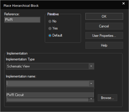
Step 24: Under Implementation, select Schematic View for the Implementation type. The Implementation Name and Path & Filename dropdowns are enabled. Select PWR Circuit for the Implementation Name.
Note: This will assign the PWR Circuit schematic to the hierarchical block.
Step 25: Click OK to place the block.
Step 26: Click to start drawing the block on the schematic canvas and click again to finish.
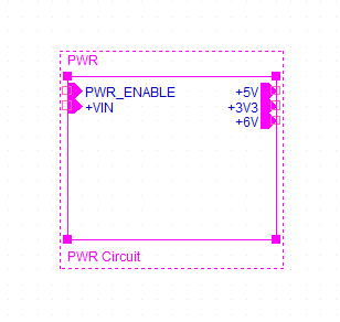
Step 27: View the block. The input and output ports defined earlier are shown on the left and right sides of the block. Ports can be adjusted as needed by clicking and dragging.
The block can now be connected within the schematic like any other component.
Step 28: Right-click the hierarchical block and select Descend Hierarchy. The PWR circuit schematic page re-opens, showing the ports added.
Wrap Up & Next Steps
Create a hierarchical schematic in OrCAD X Capture to improve schematic readability and organization for complex PCB designs. Test out this feature and more with a free trial of OrCAD X. Want to learn more about Capture? Get access to free how-tos, courses, and walk-throughs at EMA Academy.

