The metal oxide semiconductor field-effect transistor, or MOSFET, has become ubiquitous in today’s designs. MOSFETs are used for everything from switching small loads to controlling EV motor inverters; however, not all MOSFETs are created equal. Selecting the appropriate MOSFET for your application and simulating with a realistic component behavior is critical to ensure proper circuit functionality. PSpice allows you to quickly define and create the required power MOSFET SPICE model for a realistic simulation.
This quick how-to will provide step-by-step instructions on how to create a power MOSFET SPICE model in OrCAD PSpice.
To follow along, download the provided files above the table of contents.
How-To Video

Creating a Power MOSFET SPICE Model
Step 1: Open the provided design in OrCAD PSpice Designer.
Step 2: Select Place > PSpice Part > Modeling Application from the menu.
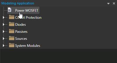
Step 3: In the Modeling Application, select Power MOSFET.
Step 4: The Power MOSFET window opens. Select the option to create an N-Channel MOSFET.
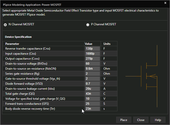
Step 5: Enter the following parameter values:
- Reverse Transfer Capacitance: 130p
- Input Capacitance: 1690p
- Output Capacitance: 270p
- Drain-to-Source Voltage: 60
- Drain-to-Source On Resistance: 9.6m
- Series Gate Resistance: 2
- Gate-to-Source Threshold Voltage: 2
- Diode Forward Voltage: 0.7
- Drain-to-Source Leakage Current: 20u
- Total Gate Charge: 43n
- Forward Transconductance: 25
- Body Diode Reverse Recovery Time: 23n
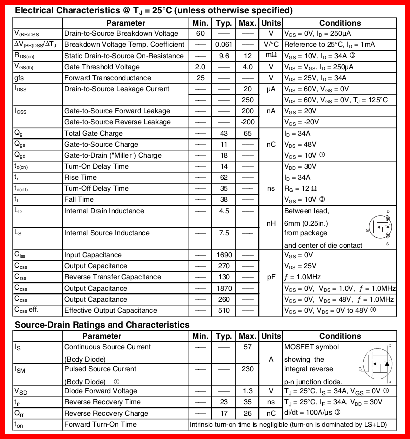
Note: Values for Power MOSFET behavior can be obtained from the component’s datasheet. Voltage for the specified total gate charge can be defined in the modeling application as well.
Learn how to decipher a Power MOSFET datasheet to determine the parameters required for SPICE Model creation here.
Step 6: Click Place to attach the component to your cursor.
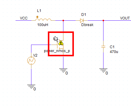
Step 7: Click to place the MOSFET in the circuit.
Running the Simulation
Step 8: Select PSpice > Run from the menu.
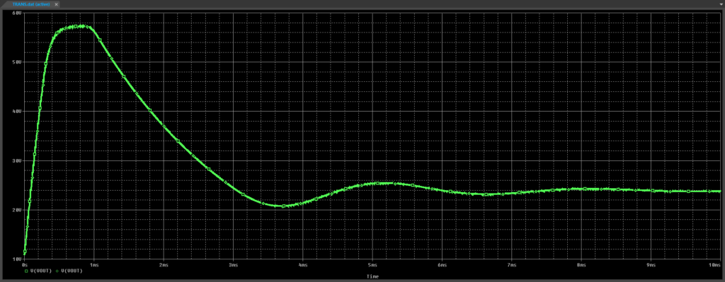
Step 9: View the simulation results. The boost converter output overshoots the desired value and has a long settling time.
Modifying the Power MOSFET SPICE Model
Step 10: Back in the schematic, select the MOSFET model and press Delete on the keyboard.
Step 11: Select the Power MOSFET option from the Modeling Application.
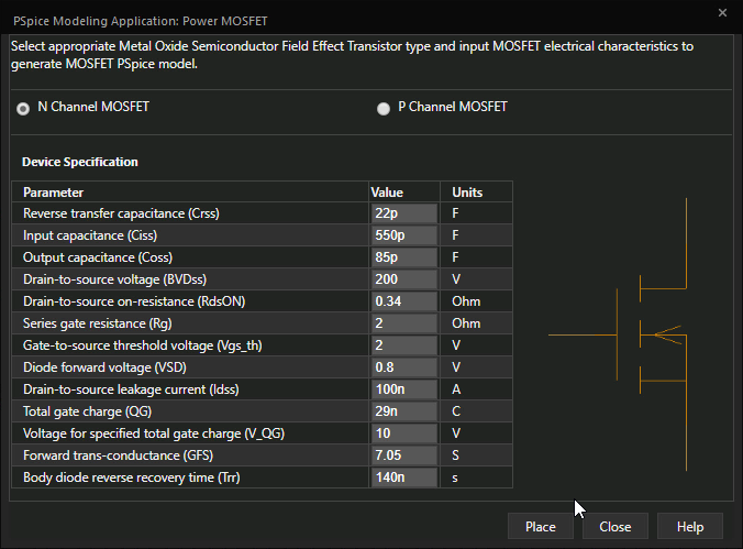
Step 12: Ensure the option to create an N-Channel MOSFET is selected. Enter the following parameter values:
- Reverse Transfer Capacitance: 22p
- Input Capacitance: 550p
- Output Capacitance: 85p
- Drain-to-Source Voltage: 200
- Drain to-Source Resistance: 0.34
- Series Gate Resistance 2
- Gate-to-Source Threshold Voltage: 2
- Diode Forward Voltage: 0.8
- Drain-to-Source Leakage Current: 100n
- Total Gate Charge: 29n
- Forward Transconductance: 7.05
- Body Diode Reverse Recovery Time: 140n
Step 13: Click Place.
Step 14: Click to place the MOSFET in the schematic.
Step 15: Select PSpice > Run from the menu.
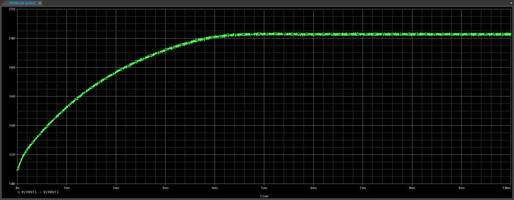
Step 16: View the simulation results. The boost converter output rises steadily and holds at just over 20V.
Wrap Up & Next Steps
Quickly create the required power MOSFET SPICE models to accurately simulate circuit behavior with the modeling application in OrCAD PSpice. Test out this feature and more with a free trial of OrCAD. To learn more about deciphering a Power MOSFET datasheet to determine the parameters required for SPICE Model creation, view our blog here.

