For a simulation that models true circuit behavior, every component model in the design must incorporate realistic characteristics. Manually creating models for every component in the design can be timing consuming, this includes the wide variety of linear and non-linear LEDs. PSpice accelerates this process with a fully configurable wizard, allowing you to quickly create LED SPICE models to accurately simulate commercially available LEDs.
This quick how-to will provide step-by-step instructions on how to create an LED SPICE model in OrCAD PSpice.
To follow along, download the provided files above the table of contents.
How-To Video
Creating an LED SPICE Model
Step 1: Open the provided design in OrCAD PSpice Designer.
Step 2: Select Place > PSpice Part > Modeling Application from the menu.
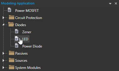
Step 3: In the Modeling Application, expand Diodes and select LED.
Step 4: The LED window opens. Enter 3.4 for the Forward Voltage and 10E-3 for the Forward Current.
Note: 10E-3 can also be entered as 10m for the Forward Current as both values will represent 10mA.
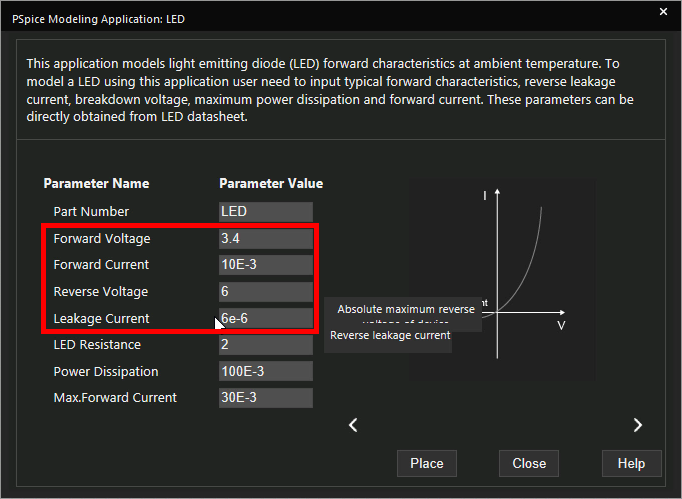
Step 5: Enter 6 for the Reverse Voltage and 6e-6 for the Leakage Current.
Learn how to determine the required parameters for a LED SPICE Model here.
Note: In the Modeling Application for LEDs, additional parameters can be set including:
- Part number
- LED resistance
- Power dissipation
- Maximum forward current
Step 6: Click Place to attach the LED to your cursor.
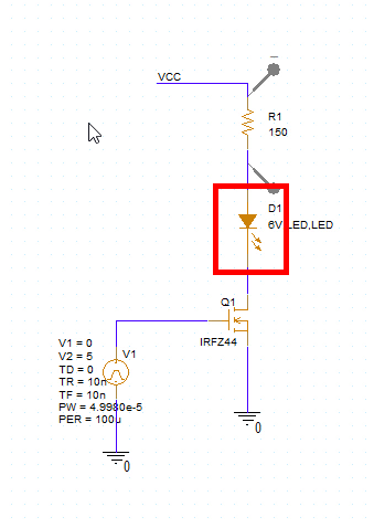
Step 7: Click to place the LED in the empty space in the schematic.
Step 8: Select PSpice > Run from the menu.
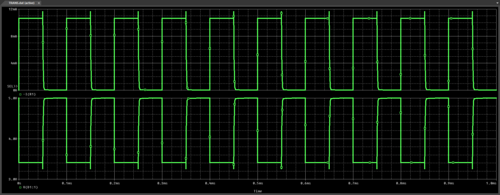
Step 9: View the simulation results. The LED voltage and current are pulsed.
Modifying the LED SPICE Model
Step 10: Back in the schematic, right-click the newly placed LED and select More > Edit PSpice Component.
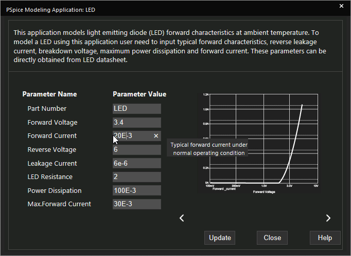
Step 11: Change the Forward Current to 20E-3. Click Update.
Step 12: Double-click the value of the resistor R1 (150).
Step 13: Change the value to 75 and click OK.
Step 14: Select PSpice > Run from the menu.
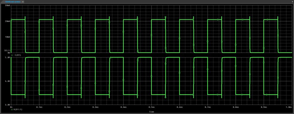
Step 15: View the simulation results. The LED voltage remains the same, but the LED current has increased significantly.
Wrap Up and Next Steps
Quickly create the required LED SPICE models and simulate accurate circuit behavior with the Modeling Application in OrCAD PSpice. Test out this feature and more with a free trial of OrCAD. To learn more about determining the required parameters for a LED SPICE Model from the device datasheet, view our blog here.

