Modeling designs helps engineers verify whether their circuit will function as intended. Modeling programs simulate circuit behavior under different conditions and in accordance with the design requirements, allowing engineers to better plan and build circuits.
Typically, to model components, generic models are used, which produce inaccurate and unrealistic simulations based on ideal conditions. This can cause functionality issues to go undetected until far later in the design process. To confidently simulate a component, create an LED SPICE model using specifications from a manufacturer’s datasheet.
What is an LED?
A Light Emitting Diode (LED) emits light when current is applied. It is used in a wide range of applications and in various fields due to its low power requirements, quick response time, and extended longevity.
What is Needed to Model an LED?
To create the required LED for simulation, manufacturer specifications for the device must be obtained:
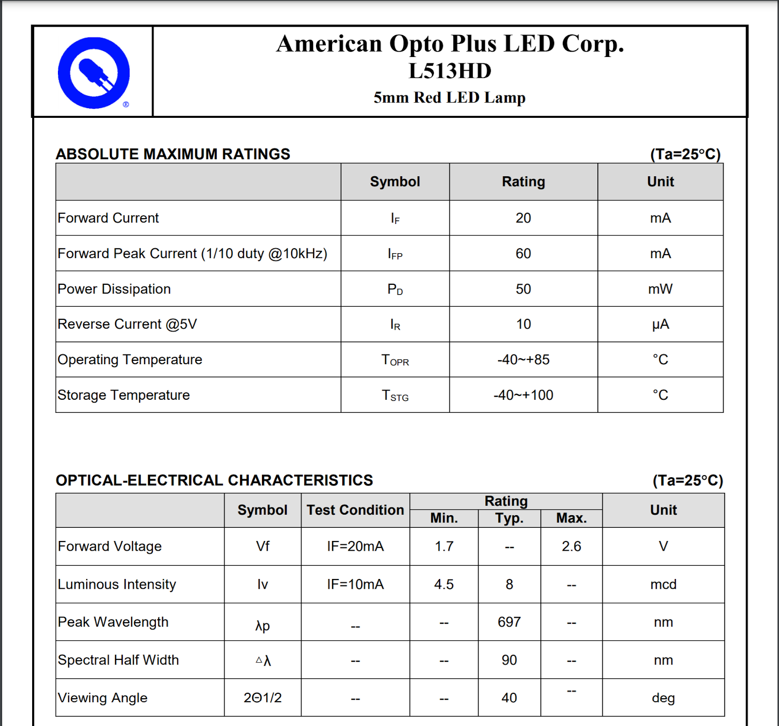
- LED Specifications:
- What are the forward and reverse voltages for the device?
- What are the forward and reverse leakage currents for the device?
- What is the power dissipation?
Once this information is obtained, these values must be incorporated into the SPICE simulation model which can be achieved by manually creating or editing a text file. Keep in mind if the LED created does not produce the intended outcome and a decision is made to change components, values will need to be edited manually. This manual process to produce an accurate LED model is time consuming and increases the likelihood of errors; however, the PSpice Modeling App provides a fast, easily configurable, and fully integrated method to create LEDs for simulation.
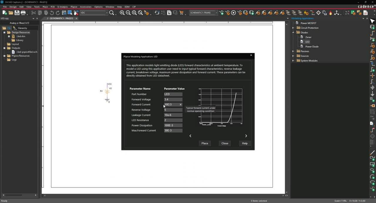
Creating an LED SPICE Model with PSpice
The LED modeling application quickly creates an LED SPICE model with a wizard-based approach. To create a model of the forward characteristics of the LED at ambient temperature, users can easily input the LED characteristics, defined by manufacturers, directly into predefined parameters:
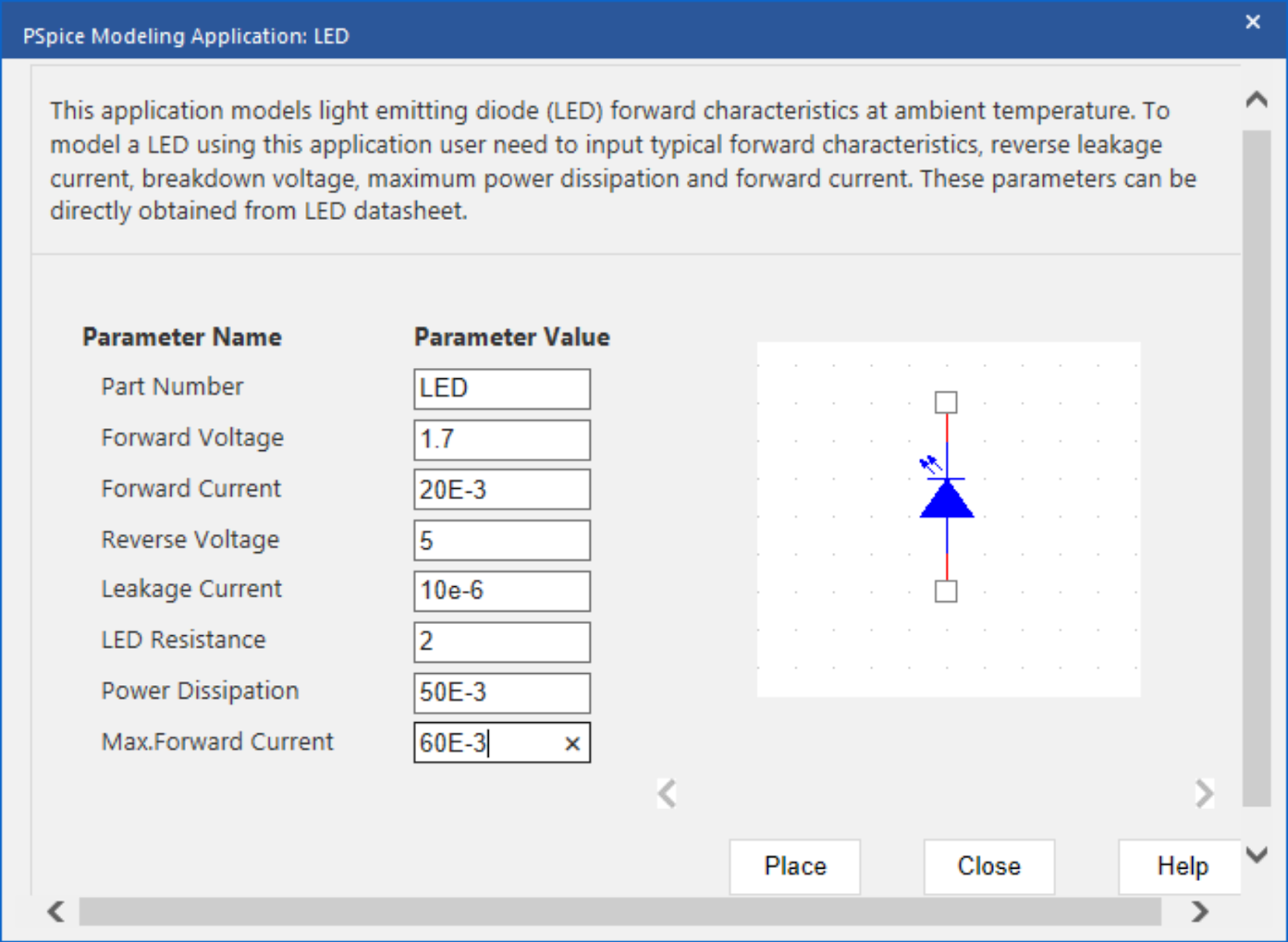
- Part Number: Specify a name for the model.
- Forward Voltage: Specify the typical forward voltage under normal operating conditions.
- Forward Current: Specify the typical forward current under normal operating conditions.
- Reverse Voltage: Specify the absolute maximum reverse voltage of the device.
- Leakage Current: Specify the reverse current or leakage current of the device.
- LED Resistance: Specify the typical resistance offered by the LED.
- Power Dissipation: Specify the absolute maximum power dissipation of the device.
- Max Forward Current: Specify the absolute maximum forward current of the device.
Using the inputted information above, the PSpice Modeling App generates a schematic symbol and automatically associates the newly created LED SPICE model without leaving the OrCAD Capture environment. The PSpice Modeling App also automatically manages the simulation profile configuration, eliminating any library set up for simulation. To try this yourself, be sure to download the Free Trial of OrCAD and check back for additional SPICE model how-tos. Click here to get the step-by-step instructions for creating a custom LED SPICE model in PSpice.