With a wide variety of diodes available and their range of varying properties, selecting the right one for your design is essential. While simulating with available SPICE models can help determine the best choice for your design, new diodes are introduced every day, and creating a new SPICE model for each one can be a tedious process. New in PSpice 24.1 is the ability to create behavioral diode models to quickly and efficiently model and simulate a fully configurable diode to determine the optimal component properties for your circuit functionality.
This quick how-to will provide step-by-step instructions on how to create behavioral diode models in PSpice Designer 24.1.
To follow along, download the provided files above the table of contents.
How-To Video
 Open in New Window
Placing a Behavioral Diode Model
Step 1: Open the provided design in PSpice Designer 24.1 or later.
Step 2: Select Place > Component from the menu to activate component placement.
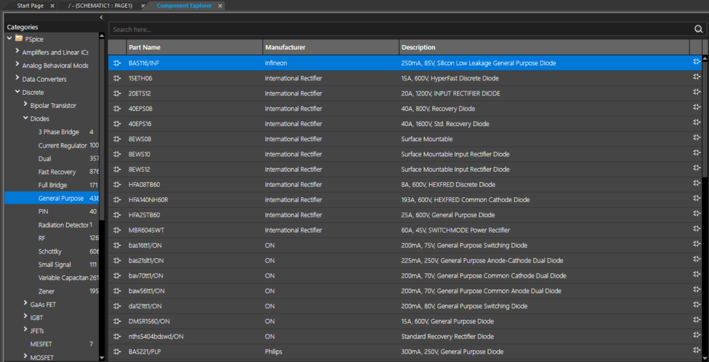
Step 3: The Component Explorer tab opens, showing a list of components that can be placed on the schematic canvas. Expand PSpice > Discrete > Diodes and select General Purpose.
Step 4: The list has been filtered to general-purpose diodes but is still quite long. To filter the list further, enter Behavioral into the Search field and press Enter.
Step 5: The list is filtered to the single entry Dbehavioral. Select the component to view its properties.
Step 6: Right-click and select Place to attach the behavioral diode model to your cursor.
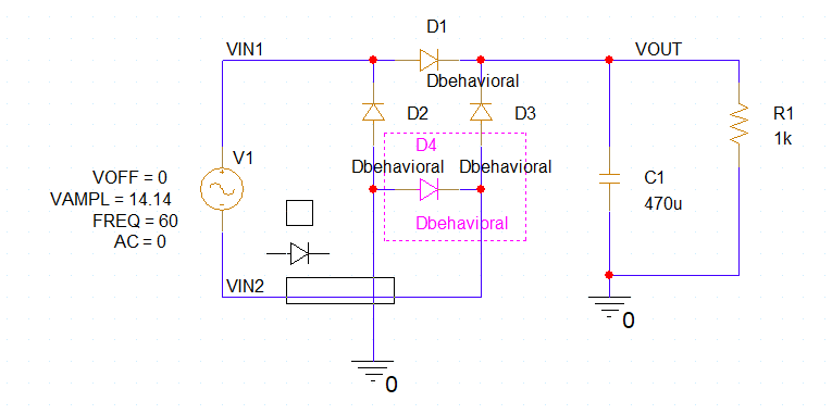
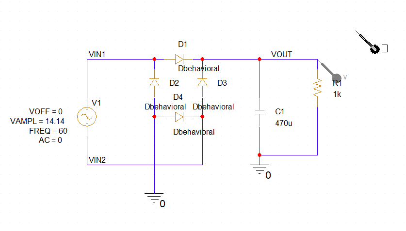
Step 7: Click to place four behavioral diode models in the schematic to form a full-bridge rectifier, as shown above. Right-click and select End Mode.
Note: Press R on the keyboard to rotate as needed.
Create Behavioral Diode Models: Rectifier Diodes
Step 8: To create behavioral diode models, parameters can be edited in the Property Editor tab. Hold CTRL on the keyboard and click to select the four diodes.
Step 9: Right-click a diode and select Edit Properties to open the Property Editor tab.
Step 10: Open the provided ER2A-L_ER2J-L(SMB).pdf datasheet in your preferred PDF viewer.
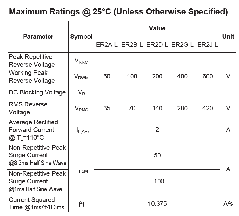
Step 11: View the Maximum Ratings table. The ER2D-L will be modeled in this example, which has a maximum peak reverse voltage of 200V and a maximum average forward current of 2A.
Step 12: To configure these in PSpice, right-click the row header for VREV and select Edit.
Step 13: Enter -200 for VREV and click OK. This will assign -200V for the reverse breakdown voltage.
Step 14: Right-click the row header for ILIMIT and select Edit.
Step 15: Enter 2 for ILIMIT and click OK. This will assign 2A for the forward current limit.
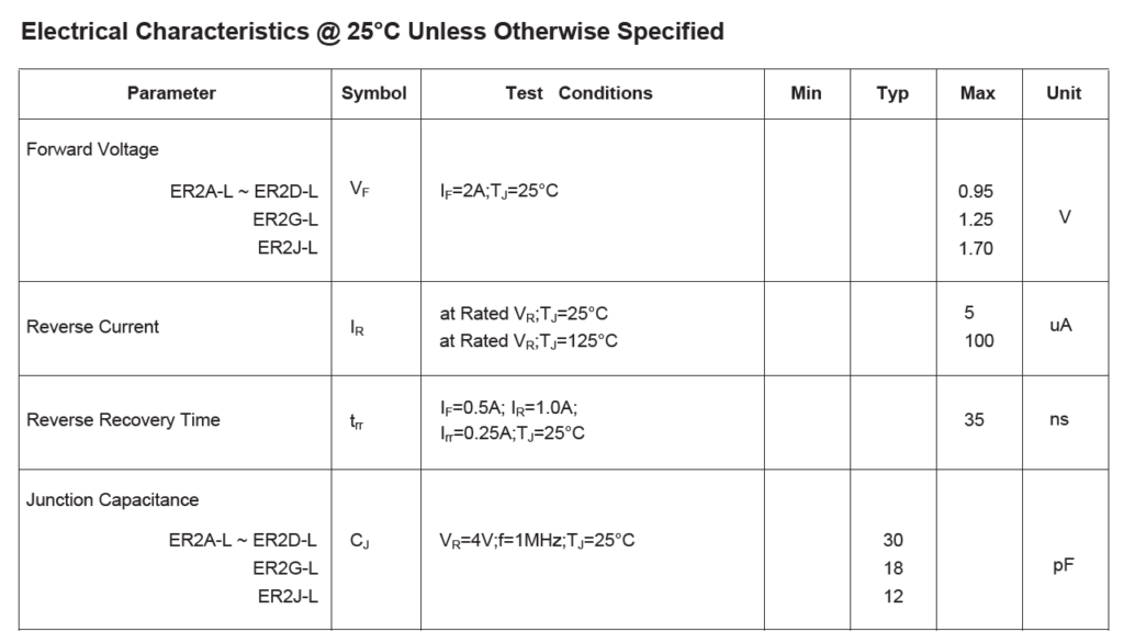
Step 16: Back in the datasheet, scroll to the second page to view the Electrical Characteristics table. The diode has a forward voltage drop of 0.95V, reverse current of 5μA, and a reverse recovery time of 35ns.
Step 17: Back in the Property Editor tab, right-click the row header for VFWD and select Edit.
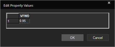
Step 18: Enter 0.95 for VFWD and click OK. This will assign a forward voltage drop of 0.95V to all selected components.
Step 19: Repeat this process for the following properties:
- REVILIMIT: -5u
- ROFF: 40meg
Note: Revilimit defines the reverse current through the diode when the breakdown voltage is exceeded. ROFF defines the resistance of the diode when it is reverse biased but is not in the breakdown region, which can be approximated by Ohm’s Law. In this example, the reverse current is defined at the rated reverse breakdown voltage.
Additional properties can be defined, such as quadratic width, temperature coefficients, and noise parameters. The complete list of parameters can be viewed by selecting Help > OrCAD Capture Help from the menu and navigating to the Behavioral Diode Model page.
Step 20: Click Apply and close the Property Editor tab.
Simulating Behavioral Diode Models: Rectifier Diodes
Step 21: A simulation profile must be created to simulate the new model. Select PSpice > New Simulation Profile from the menu.
Step 22: The New Simulation window opens. Enter Diode_Trans for the simulation name and click Create.
Note: If the Simulation Manager Product Choices window opens, select the appropriate license and click OK.
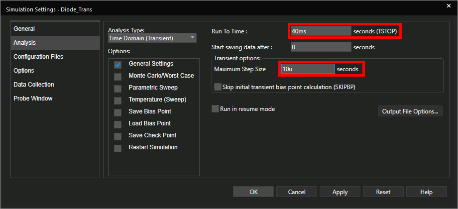
Step 23: The Simulation Settings window opens. Enter 40ms for the Run To Time and 10u for the Maximum Step Size. Leave the other settings as the defaults and click OK.
Step 24: To plot simulation results, probes must be placed on the schematic. Select the Voltage/Level Marker button from the toolbar.
Step 25: Click to place a probe on the VOUT net. Right-click and select End Mode.
Step 26: Select PSpice > Run from the menu to start the simulation.
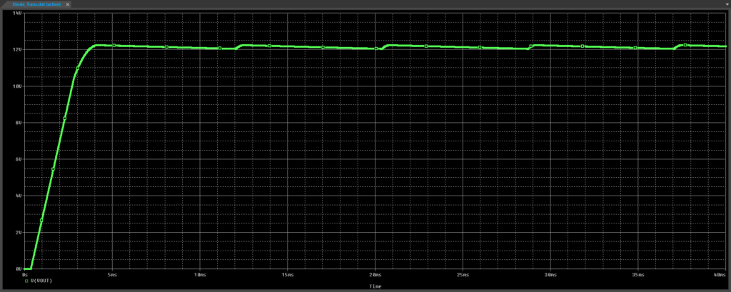
Step 27: View the simulation results. The output voltage rises to 14.14V minus the diode drop and holds above 12V with some ripple, as expected.
Create Behavioral Diode Models: Zener Diodes
Step 28: Close the PSpice A/D window. Back in Capture, select the Component Explorer tab to reopen the component placement list.
Step 29: Double-click the Dbehavioral entry on the part list to attach it to your cursor.
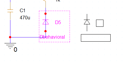
Step 30: Click to place the behavioral diode model between R1 and ground. Right-click and select End Mode when finished.
Step 31: The wire segment between the anode and cathode will remain intact and must be removed for the simulation to run. Select the wire segment and press Delete on the keyboard.
Step 32: Right-click the diode and select Edit Properties to define the Zener diode properties.
Step 33: Open the provided ds18010.pdf datasheet in your preferred PDF viewer.
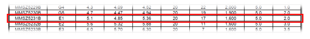
Step 34: Scroll to the second page and view the Electrical Characteristics table. For this example, the MMSZ5231B will be modeled, so all parameters will be taken from that row.
Step 35: Back in the Property Editor tab, select the cell for each of the following rows for the selected diode and enter the following values.
- ILIMIT: 20m
- RBRK: 17
- REVILIMIT: –20m
- ROFF: 400k
- RON: 17
- VFWD: 0.9
- VREV: -5.1
Step 36: Click Apply and close the Property Editor tab.
Simulating Behavioral Diode Models: Zener Diodes
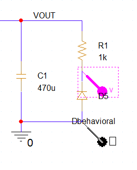
Step 37: Back in the schematic canvas, click and drag the probe to move it to the net between the Zener diode and R1 to plot the Zener voltage.
Step 38: Select PSpice > Run from the menu.
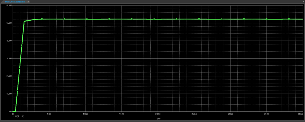
Step 39: View the simulation results. The voltage at this junction holds at approximately 5.1V.
Wrap Up & Next Steps
Create behavioral diode models with full customization of diode parameters for quick, easy, and efficient diode simulation in PSpice Designer 24.1. Test out this feature and more with a free trial of OrCAD. Want to learn more about PSpice? View additional how-tos, walk-throughs, and courses at EMA Academy.

