While OrCAD X Presto includes a standard library of commonly used footprints; however, with the influx of new, cutting-edge electronic devices into the market, it is likely some footprints will need to be created for your PCB designs. Creating a footprint from scratch can be done manually but is very time-consuming and can be prone to errors. New in OrCAD X Presto 24.1 is the ability to create PCB footprints from templates with a simple wizard-based generator, saving design time and energy.
This quick how-to will provide step-by-step instructions on how to create PCB footprints from a template in OrCAD X Presto Professional.
To follow along, download the provided files above the table of contents.
How-To Video
 Open in New Window
Activate the Footprint Generator
Step 1: Open OrCAD X Presto Professional 24.1 or later.
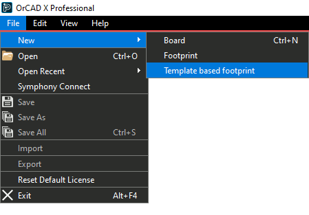
Step 2: Select File > New > Template Based Footprint from the menu.
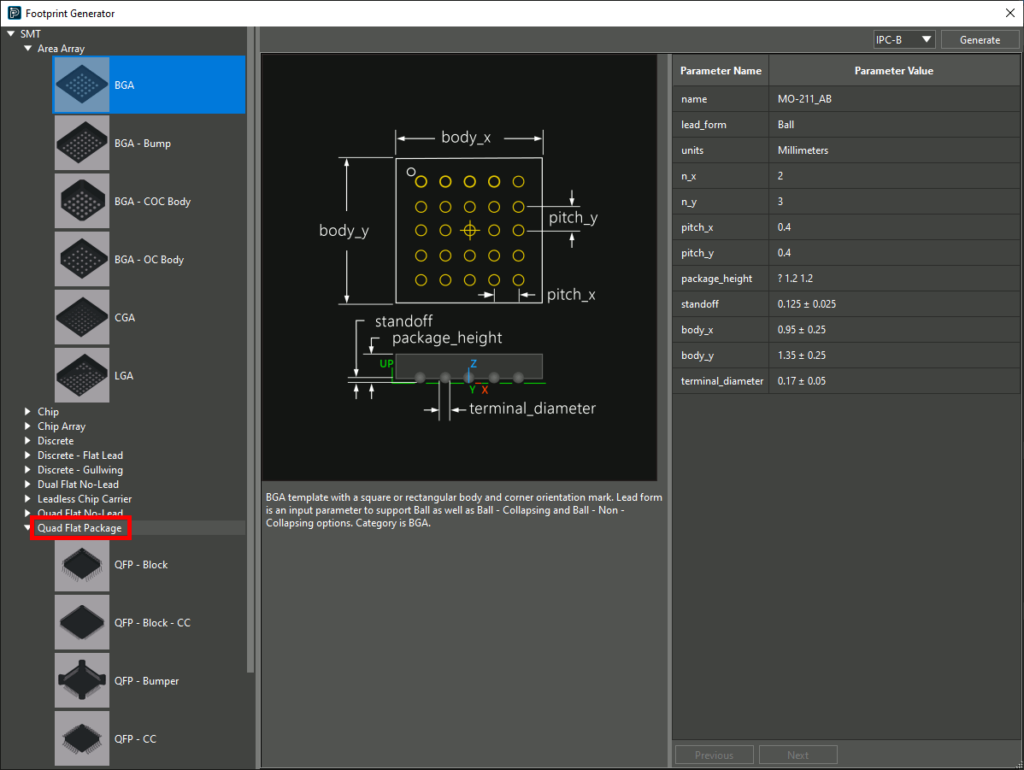
Step 3: The Footprint Generator opens. Expand SMT > Quad Flat Package to start creating the footprint.
Step 4: Select QFP – Block. The graphic changes to that of a QFP chip.
Define the Footprint Parameters
Step 5: In this example, we will create the footprint for an ATMEGA4809 microcontroller. Information to create the footprint can be found in the provided datasheet. Open the provided ATMEGA4809.pdf in a PDF viewer.
Step 6: Navigate to page 5 of the datasheet. A table of part dimensions is shown.
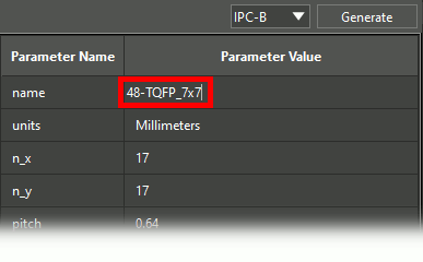
Step 7: In the Presto Footprint Generator, enter 48-TQFP_7x7 for the footprint name.
Step 8: Double-click the cell for Units to open a drop-down menu for the units. Select Millimeters.
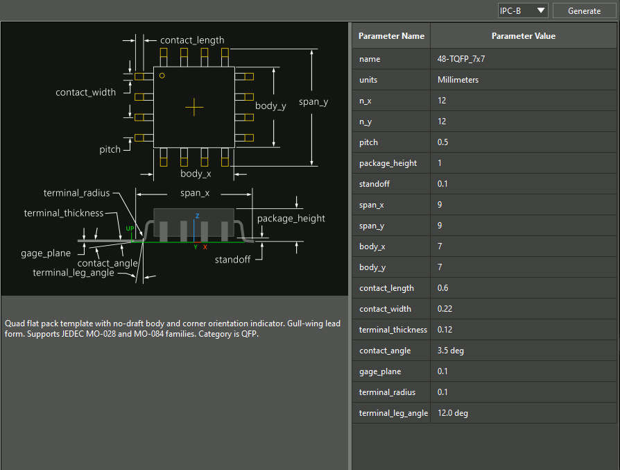
Step 9: Enter the following values for each parameter, as obtained from the dimension table for the ATMEGA4809. Start by defining pin pitch parameters.
- n_x: 12 (number of pins on horizontal axes)
- n_y: 12 (number of pins on vertical axes)
- Pitch: 0.5 (pin pitch)
Step 10: Define the body parameters for the chip.
- Package Height: 1 (total IC package height)
- Standoff: 0.1 (the height of the bottom of the chip above the board)
- Span_x: 9 (the total width of the chip, including pin length)
- Span_y: 9 (the total height of the chip, including pin length)
- Body_x: 7 (the total width of the chip, excluding pin length)
- Body_y: 7 (the total height of the chip, excluding pin length)
Step 11: Define individual pin contact parameters for the chip.
- Contact Length: 0.6 (the length of the portion of each pin that makes contact with the board)
- Contact Width: 0.22 (the width of each pin)
- Terminal Thickness: 0.12 (the thickness of each pin)
- Contact Angle: 3.5 deg (the angle at which each pin makes contact with the board)
- Gage Plane: 0.1 (the height above the board at which each pin terminates)
- Terminal Radius: 0.1 (the radius of the bend the pin takes to make contact)
- Terminal Leg Angle: 12 deg (the vertical angle at which each pin connects from the body of the chip to the pad)
Note: If dimensions are shown visually in the datasheet, use the infographic to the left of the table to determine which dimensions map to which parameters.
Create PCB Footprints
Step 12: Select the desired IPC standard from the dropdown at the top of the window. For this example, select IPC-B.
Step 13: Click Generate to create the part and close the window.
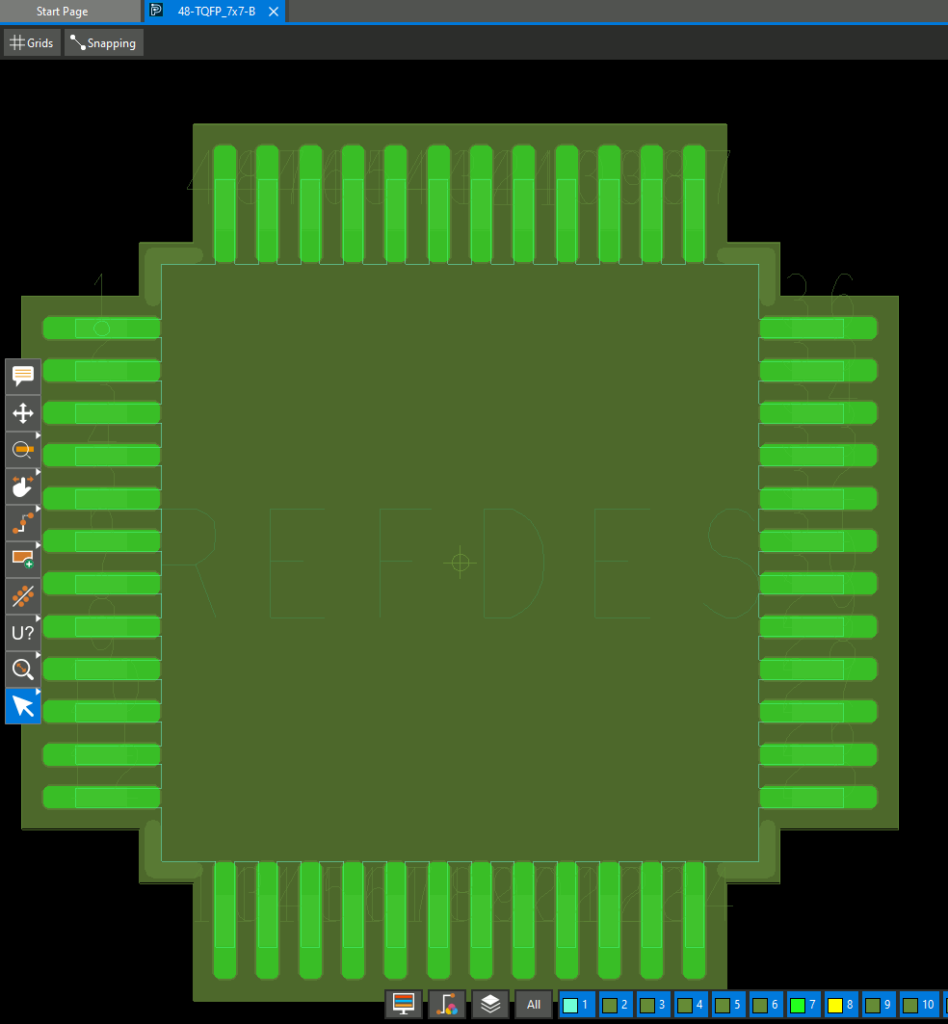
Step 14: View the PCB canvas. A 48-pin, 7mm×7mm footprint is shown.
Step 15: Select File > Save from the menu. The footprint can now be used in future designs in Allegro or Presto.
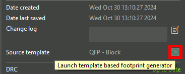
Note: If any changes need to be made to the footprint, select the Launch symbol for Source Template in the Properties panel to open the footprint wizard, edit the values, and regenerate the footprint.
View the 3D Model
Step 16: A 3D model was generated for the footprint as well. To view the model, open the Visibility panel and select the Display mode.
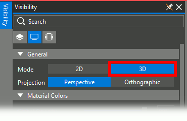
Step 17: Under Mode, select 3D.
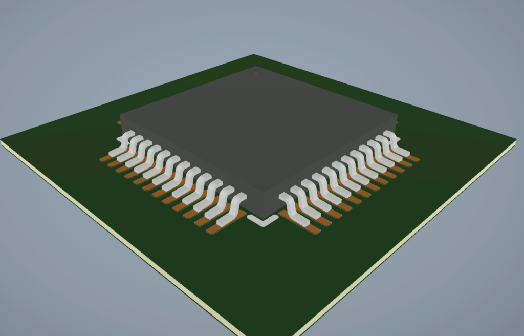
Step 18: A 3D rendering of the QFP chip is shown in the Presto canvas. Click and drag the middle mouse button to pan the view and hold Shift on the keyboard while dragging the middle mouse button to rotate.
Wrap Up & Next Steps
Quickly and easily create PCB footprints from a template using the wizard-based generator included in OrCAD X Presto. Test out this feature and more with a free trial of OrCAD X Presto. For more how-tos and step-by-step walk-throughs, visit EMA Academy.