While schematic symbols are often provided by manufacturers and verified sources like Ultra Librarian, sometimes schematic symbols are not available and must be created to ensure clear communication of the components in the design. OrCAD X Capture allows designers to quickly create schematic symbols, define reference designators, and associate PCB footprints to clearly communicate components in your PCB designs.
This quick how-to will provide step-by-step instructions on how to create schematic symbols in OrCAD X Capture.
To follow along, download the provided files above the table of contents.
How-To Video
 Open in New Window
Create Schematic Symbols: Libraries
Step 1: Open the provided design in OrCAD X Capture.
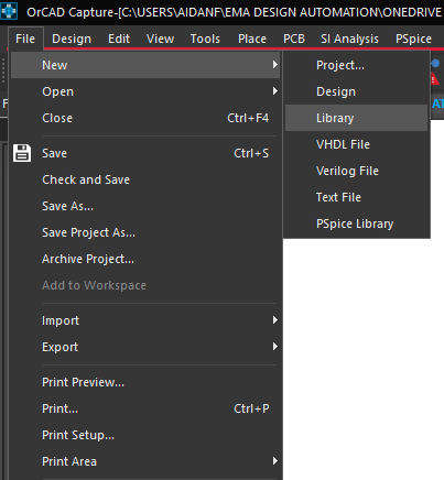
Step 2: For this example, we will create a new library for the new part. Select File > New > Library from the menu.
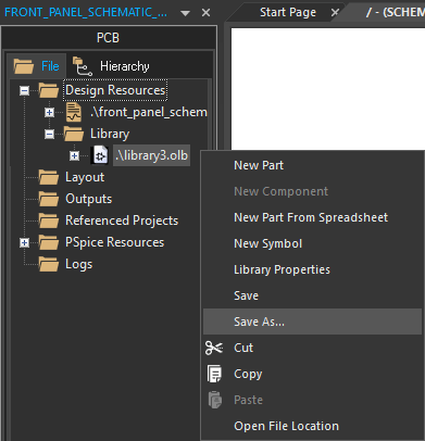
Step 3: The new library is added to the Library folder in the Project Manager. To name the library, right-click and select Save As.
Step 4: Browse to the working directory. Enter the name Rotary_Encoder.olb for the library and click Save.
Create Schematic Symbols: Parts
Step 5: To create a part, right-click the library and select New Part.
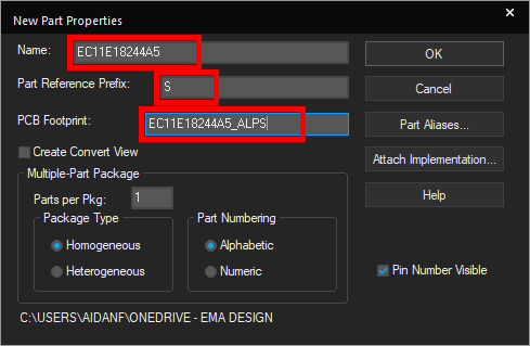
Step 6: The New Part Properties window opens. Enter EC11E18244A5 for the part name and S for the Part Reference Prefix.
Step 7: Enter EC11E18244A5_ALPS for the PCB footprint.
Note: The PCB footprint has already been created and defining the name will associate the model with the schematic symbol. Check out these step-by-step instructions for help with creating PCB footprints in OrCAD X.
Step 8: Click OK to create the part. The Part Editor tab opens.
Create Schematic Symbols: Draw a Part
Step 9: The Part Editor tab opens to a blank canvas with a square outline for the new part. Click the outline to select it.
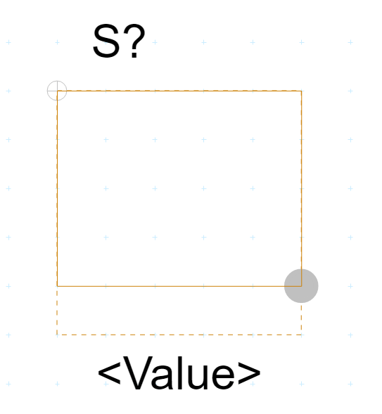
Step 10: Click and drag the bottom-right corner of the outline to reduce the height by one grid space.
Step 11: Select Place > Rectangle from the menu to draw the part body.
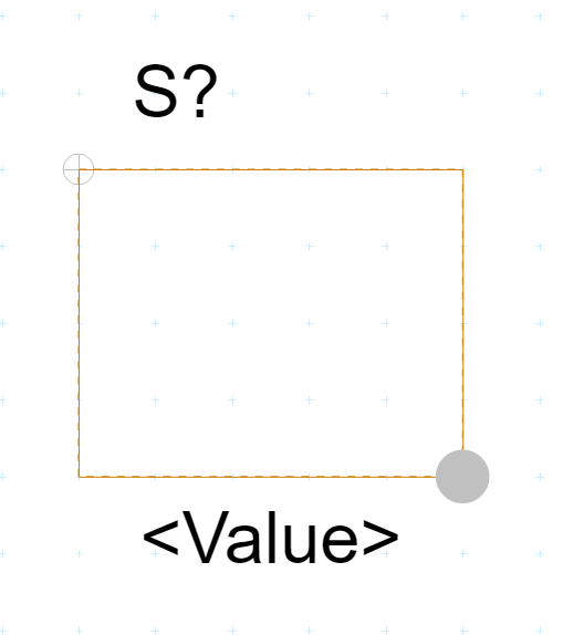
Step 12: Click to start drawing the rectangle at the upper-left corner of the part and click the bottom-right corner to finish.
Note: More complex shapes can be drawn with the Polyline feature.
Create Schematic Symbols: Define Pins
Step 13: With the part body drawn, pins should be defined next. To define pins, select Place > Pin from the menu.
Step 14: The Place Pin window opens. Here you can define the pin name, number, shape, type, and width. Enter A for the name and 1 for the number.
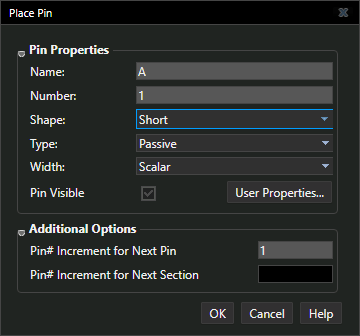
Step 15: Set the Shape to Short, the Type to Passive, and the Width to Scalar.
Step 16: Click OK. Click to place the pin in the upper-left corner of the symbol.
Step 17: Press Shift-G on the keyboard to re-open the Place Pin window.
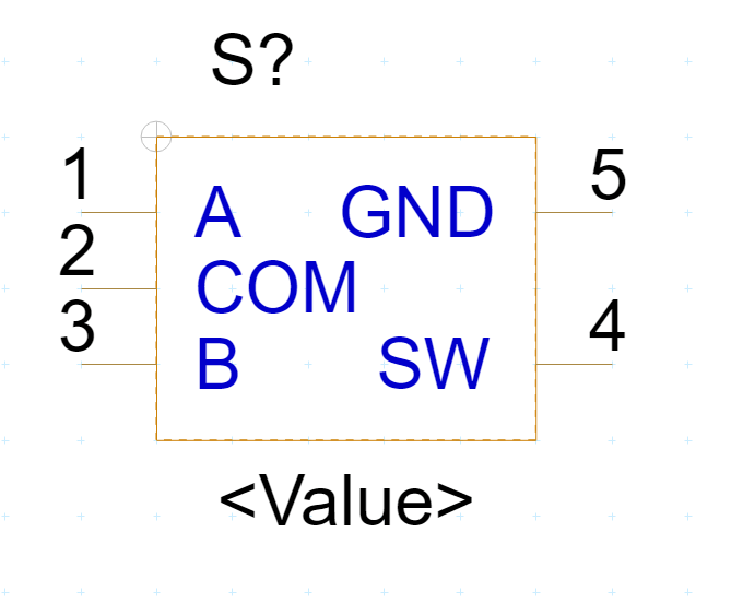
Step 18: Repeat steps 13-16 to place pins with the following names counterclockwise around the symbol, as shown above. When finished, right-click and select End Mode.
- COM
- B
- SW
- GND
Note: The pin number increments automatically. All pins in this component are short, passive, and scalar; however, the following options are available:
- Clock
- Dot
- Dot-Clock
- Line
- Short
- Short Clock
- Short Dot
- Short Dot Clock
- Zero Length
Step 19: Right-click the Part Editor tab and select Save to save the part. Close the tab. The part has been defined.
Placing the Part
Step 20: To place the newly drawn part, select Place > Part from the menu.
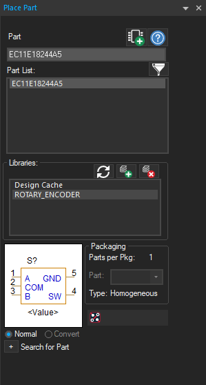
Step 21: The Place Part panel opens with the Rotary_Encoder library added. Select the library from the Libraries list.
Step 22: Select the part from the list at the top. A preview is shown towards the bottom of the panel.
Step 23: Click Place Part or double-click the listing to attach the part to your cursor.
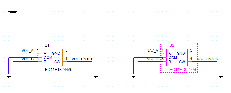
Step 24: Click to place two instances of the rotary encoder in the empty spaces in the schematic. Right-click and select End Mode.
Note: The reference designator is incremented automatically. Learn more about annotating reference designators with this how-to.
Step 25: Right-click one of the instances and select Edit Properties.
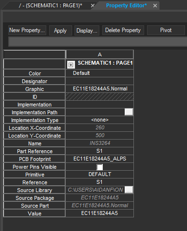
Step 26: The Property Editor tab opens, showing a table of part properties. The assigned part number (under Value) and PCB footprint are shown.
Wrap Up & Next Steps
Quickly and easily create schematic symbols to ensure clear communication of components with OrCAD X Capture. Test out this feature and more with a free trial of OrCAD X. Want to learn more about Capture? Get access to free how-tos, courses, and walk-throughs at EMA Academy.

