For any modern AC-powered electronic device, often the first step of the design is to convert the AC power into something useful; the transformer is one of the most important components to accomplish this. Modeling accurate transformer characteristics in your SPICE simulations is critical to ensure proper operation as the transformer behavior will vary based on power requirements, the region in which the device is to be used, and physical size. PSpice allows you to quickly define and create the required transformer SPICE models for a realistic simulation.
This quick how-to will provide step-by-step instructions on how to create a transformer SPICE model in OrCAD PSpice.
To follow along, download the provided files above the table of contents.
How-To Video

Creating a Transformer SPICE Model
Step 1: Open the provided design in OrCAD PSpice Designer.
Step 2: Select Place > PSpice Part > Modeling Application from the menu.
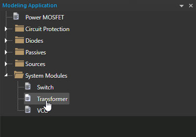
Step 3: In the Modeling Application, expand System Modules and select Transformer.
Step 4: The Transformer window opens. Select Centre Tap for the transformer configuration.
Note: Additional transformer configurations available include:
- Two Winding
- Custom Tap
- Flyback
- Forward
- Forward with Reset Winding
Step 5: Set the Primary Winding Inductance to 5 and the Turn Ratio to 0.1.
Note: This will create a transformer with 10× the number of turns on its primary winding as its secondary. Learn how to decipher a transformer datasheet to determine the parameters required for SPICE Model creation here.
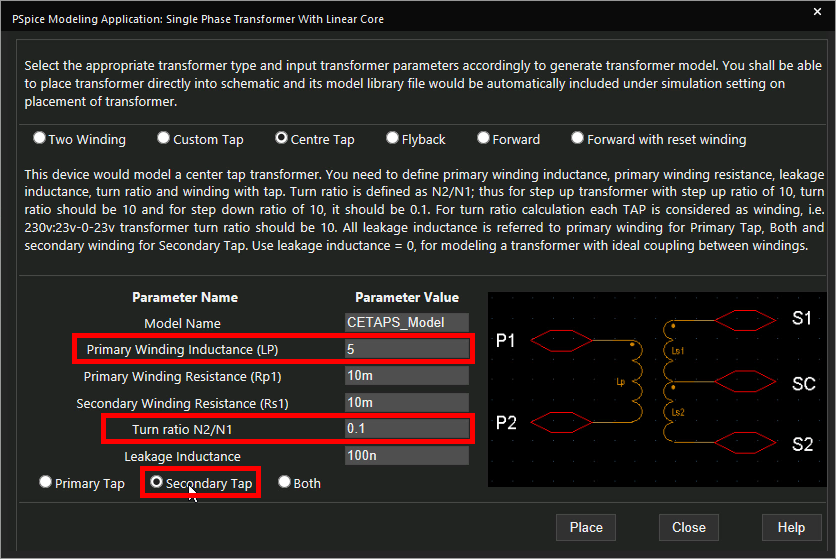
Step 6: Select Secondary Tap to define the center tap on its secondary winding.
Step 7: Select Place to attach the transformer to your cursor.
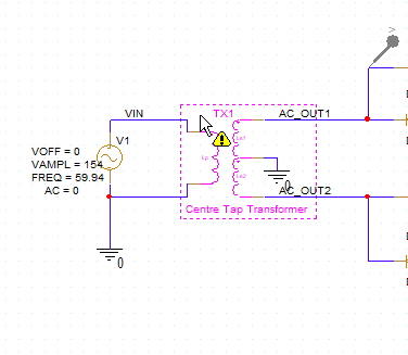
Step 8: Click to place the transformer in the circuit.
Running the Simulation
Step 9: Select PSpice > Run from the menu.
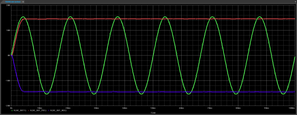
Step 10: View the simulation results. The transformer output is a sine wave and the positive and negative outputs of the rectifier circuit are of equal magnitude.
Modifying the Transformer SPICE Model
Step 11: Back in the schematic, select the transformer model and press Delete on the keyboard.
Step 12: Select the System Modules > Transformer option from the Modeling Application.
Step 13: Select Custom Tap for the transformer configuration.
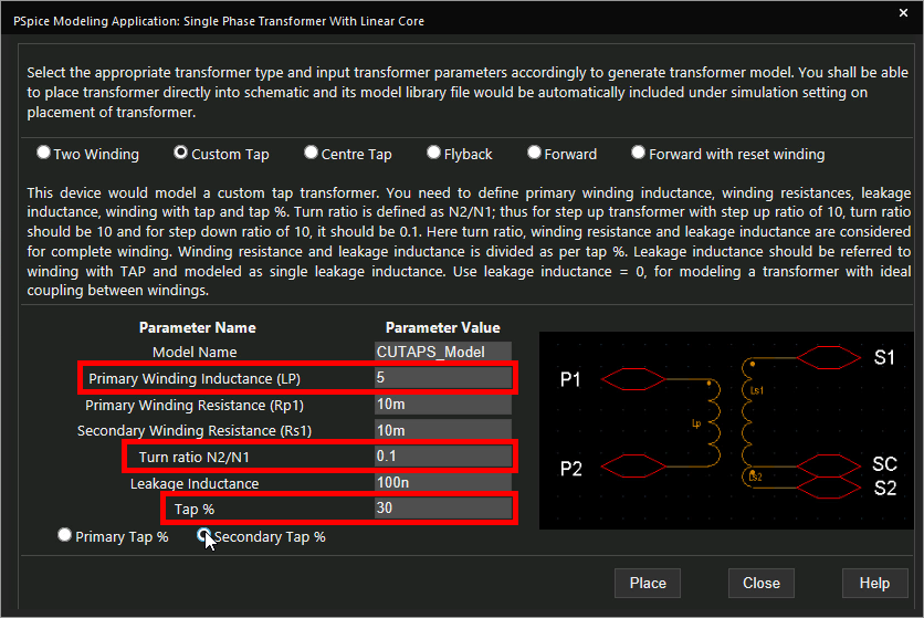
Step 14: Set the Primary Winding Inductance to 5, the Turn Ratio to 0.1, and the Tap % to 30.
Note: This will create a transformer with an asymmetrical tap.
Step 15: Select Secondary Tap to define the tap in the secondary winding.
Step 16: Select Place.
Step 17: Click to place the transformer in the schematic.
Step 18: Select PSpice > Run from the menu.
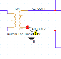
Step 19: Click and drag to adjust the ground wire to connect it to the offset center.
Step 20: Select PSpice > Run from the menu.
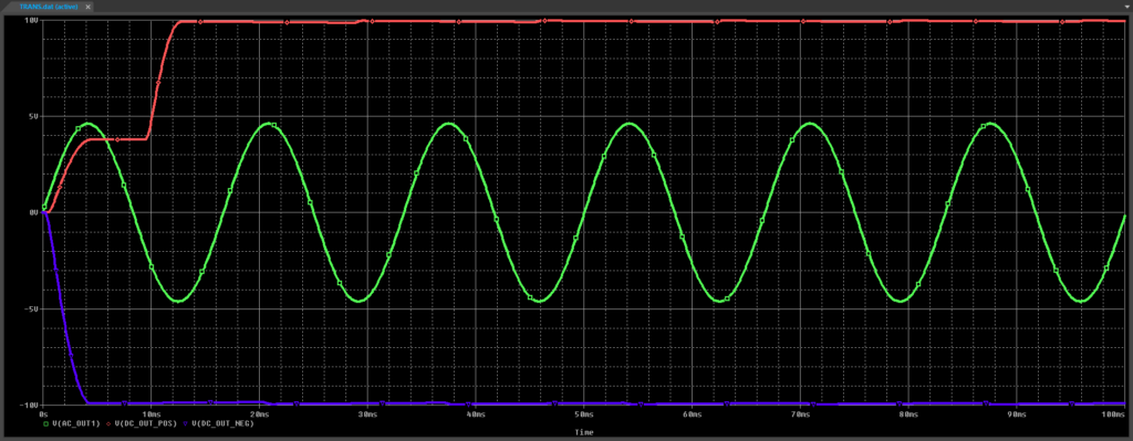
Step 21: View the simulation results. The AC output is lower at the AC_OUT_1 probe.
Wrap Up & Next Steps
Quickly create the required transformer SPICE models to accurately simulate circuit behavior with the modeling application in OrCAD PSpice. Test out this feature and more with a free trial of OrCAD.
Learn how to decipher a transformer datasheet to determine the parameters required for SPICE Model creation here.
