Modeling designs helps engineers verify whether their circuit will function as intended. Modeling programs simulate circuit behavior under different conditions and in accordance with the design requirements, allowing engineers to better plan and build circuits.
Typically, to model components, generic models are used, which produce inaccurate and unrealistic simulations based on ideal conditions. This can cause functionality issues to go undetected until far later in the design process. To confidently simulate a component, create a transformer SPICE model using specifications from a manufacturer’s datasheet.
What is a Transformer?
A transformer is a passive electrical device that transfers electric energy from one circuit to another. Changes in electric current flowing through the primary coil, induce current in another coil called the secondary. Transformers are most commonly used to either increase (step up) or reduce (step down) the voltage.
What is Needed to Model a Transformer?
To create the required transformer for simulation, two items must be defined:
- Type:
- Which type of transformer is required: two-winding, custom tap, center tap, flyback, forward, or forward with reset winding?
- Transformer Specifications:
- What are the specifications of the transformer: winding inductance, winding resistance, etc.?
Once this information is obtained, these values must be incorporated into the SPICE simulation model which can be achieved by manually creating or editing a text file. Keep in mind if the transformer created does not produce the intended outcome and a decision is made to change components, values will need to be edited manually. This manual process to produce an accurate transformer model is time consuming and increases the likelihood of errors; however, the PSpice Modeling App provides a fast, easily configurable, and fully integrated method to create a transformer SPICE model for simulation.
Creating a Transformer SPICE Model with PSpice
The transformer modeling application quickly creates a transformer SPICE model in various configurations with a wizard-based approach:
- Two-Winding: Generates a model for a simple two-winding transformer.
- Custom Tap: Generates a model for a custom tap transformer.
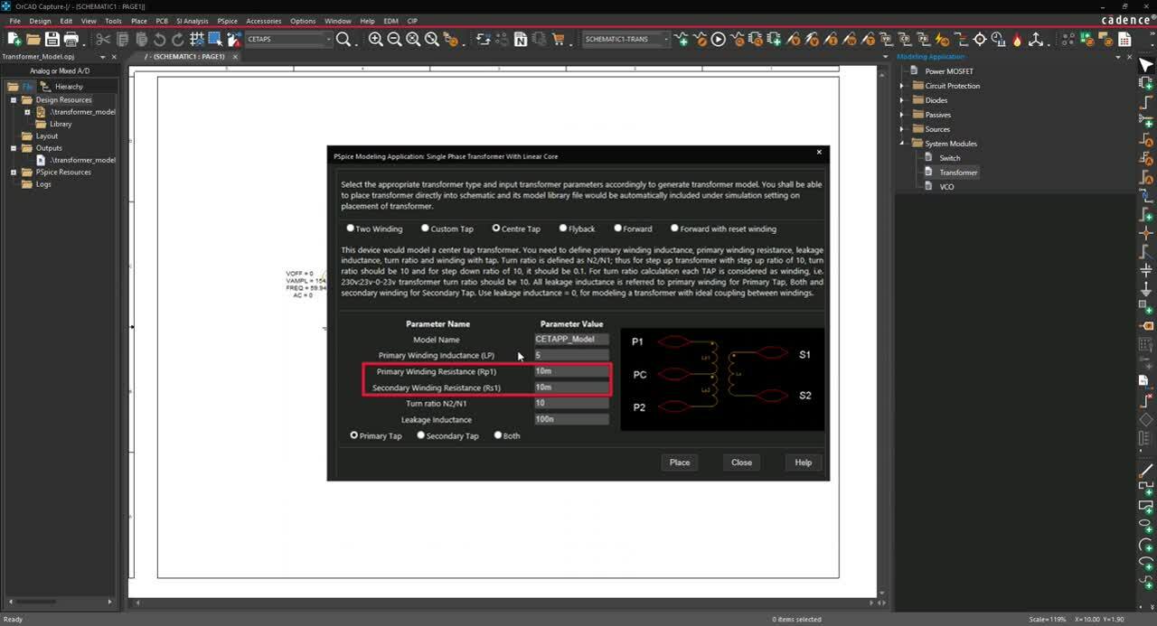
- Center Tap: Generates a model for a center tap transformer.
- Flyback: Generates a model for a single-ended, flyback converter transformer.
- Forward: Generates a model for a single-ended, forward converter transformer.
- Forward with Reset Winding: Generates a model for a single-ended forward converter transformer with auxiliary reset winding.
Based on the transformer configuration, the modeling application will define the required parameters. To create a transformer SPICE model, users can easily input the transformer characteristics, defined by manufacturers, directly into predefined parameters. Every transformer requires the following:
- Model Name: Specify a name for the model.
- Primary Winding Inductance: Specify the primary winding inductance or magnetizing inductance to determine the flux that will link the cores.
- Primary Winding Resistance: Specify the resistance of the primary winding.
- Secondary Winding Resistance: Specify the resistance of the secondary winding.
- Turn Ratio: Specify the turn ratio. This is the ratio of the number of turns for the secondary winding (N2) by the number of turns for the primary winding (N1).
- Leakage Inductance: Specify the leakage inductance or the energy stored in the non-magnetic regions between windings. This is a result of imperfect flux coupling.
Some transformers have unique requirements. The PSpice Modeling App takes away the guesswork with pre-defined templates customized for each transformer type to quickly create transformer SPICE models.
Center Tap Transformer
For a center tap transformer, easily select the tap for which the parameters are defined:
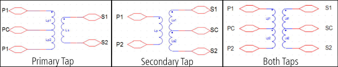
- Only the primary winding
- Only the secondary winding
- Both windings
Custom Tap Transformer
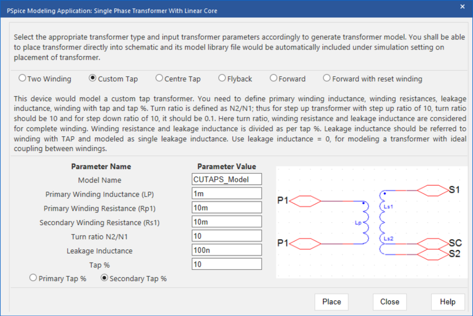
For a custom tap transformer, easily assign parameters to the primary or secondary windings and define the tap percentage.
- Tap Percentage:
The tap percentage specifies where the tap is required to achieve the desired turns ratio. When Primary % is selected, the tap percentage is specified for the primary winding. When Secondary % is selected, the tap percentage is specified for the secondary winding.
Forward Transformer with Reset Winding
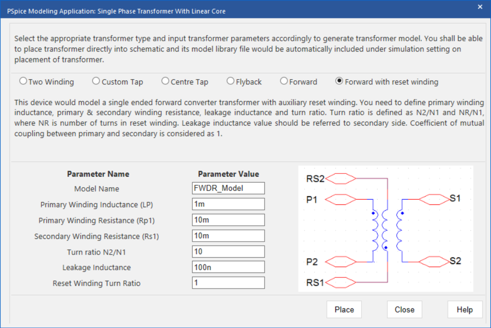
For a forward transformer with reset winding, an additional parameter is required:
- Reset Winding Turn Ratio:
The reset winding turn ratio is the ratio of the reset turns to the primary winding.
Using the inputted information above, the PSpice Modeling App generates a schematic symbol and automatically associates the newly created transformer SPICE model without leaving the OrCAD Capture environment. The PSpice Modeling App also automatically manages the simulation profile configuration, eliminating any library set up for simulation. To try this yourself, be sure to download the Free Trial of OrCAD. Check back for additional SPICE model how-tos and get step-by-step instructions to create Transformer SPICE models in PSpice here.


