Via arrays are structured groupings of vias which can help to improve signal integrity, thermal management, current handling and EMI/EMC performance. Designers often create via arrays for:
- Fanouts
- Heat sinking
- Stitching or shielding
Manually placing vias for an array can be time-consuming, imprecise, and can lead to inadequate via array design. OrCAD X Presto enables you to easily create via arrays along traces, shape edges, and custom area groupings.
This quick how-to will provide step-by-step instructions on how to create via arrays in OrCAD X Presto.
To follow along, download the provided files above the table of contents.
How-To Video
 Open in New Window
Configuring Via Array Settings
Step 1: Open the provided design in OrCAD X Presto.
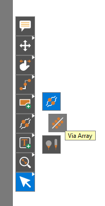
Step 2: Right-click the Structure mode in the toolbar and select Via Array.
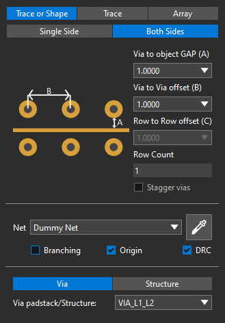
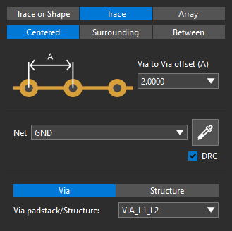
Step 3: The Via Array widget opens. Select Trace or Shape to surround a trace with vias. Here you can choose the type of via structure to create, offsets, the net to connect the vias to, and more. Each type of via structure has its own settings.
Step 4: Select the Pick button with the eyedropper icon to define the via net.
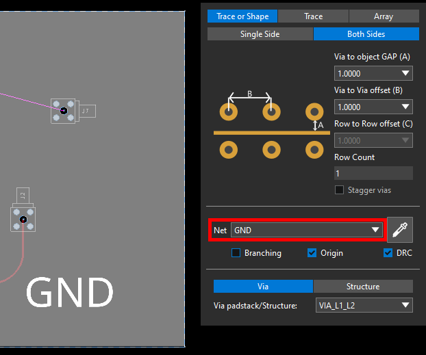
Step 5: Select the GND plane. The GND net is automatically assigned.
Note: This determines the net the via array will connect to. In this example, all generated vias will connect to the GND net. Alternatively, select the desired net from the drop-down menu.
Surrounding a Trace with Vias
Step 6: Scroll up to zoom into the SIG14 trace in the top-left corner of the board.
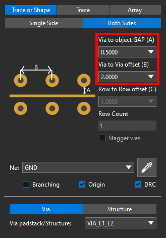
Step 7: In the Via Array widget, set the Via to Object Gap to 0.5 and the Via to Via Offset to 2.
Note: These values are shown as dimensions in the pictorial on the left side of the widget.
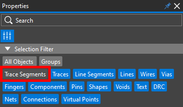
Step 8: Uncheck Trace Segments in the Selection Filter subpanel of the Properties panel. This will make for easier trace selection and allow the array to be adjusted during placement.
Step 9: Select the trace. Adjustable via arrays are attached to both sides.
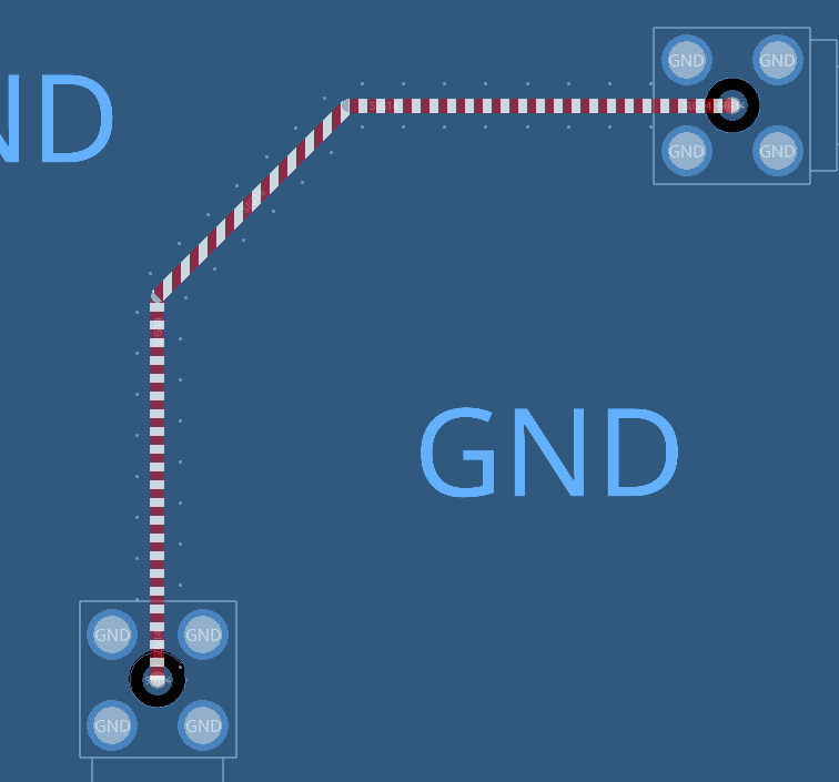
Step 10: Click again to place the arrays. Shielding has been added to the trace.
Adding Multiple Via Rows
Step 11: Hold the middle mouse button to pan the view to the curved trace in the bottom-right corner of the board.
Note: Alternatively, use the directional arrows on the keyboard to pan the view.
Step 12: Select Trace in the Via Array widget. A new set of options is listed.
Note: In this mode, you can create centered or surrounding vias for a single trace, or place a via array between two traces.
Step 13: Select Surrounding to add surrounding vias.
Step 14: Enter 2 for the Row Count and check Stagger Vias. This will surround the trace with two rows of staggered vias, as shown in the pictorial.
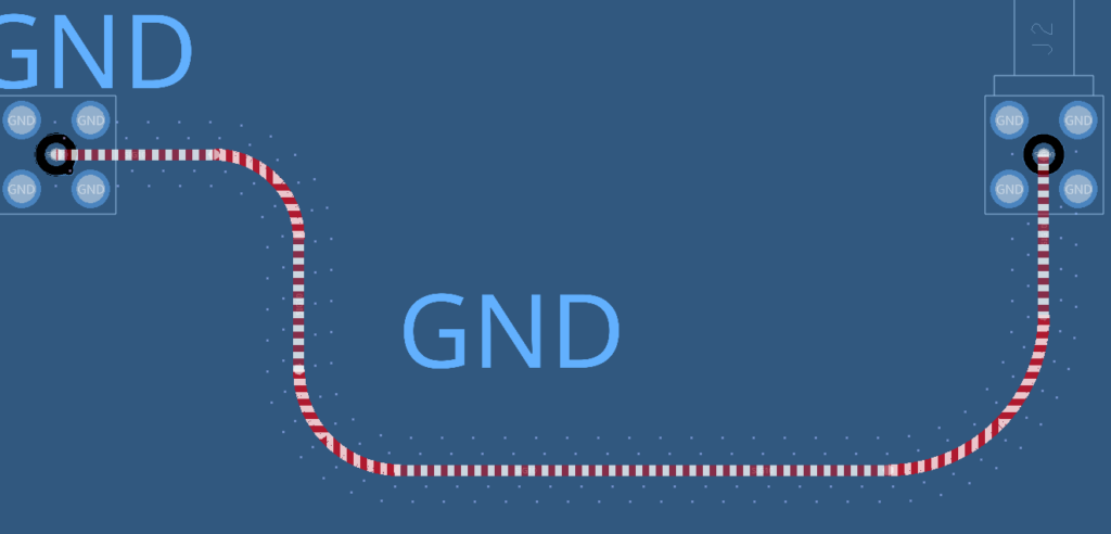
Step 15: Select the trace to create the via array preview. Click outside the trace to place the vias.

Note: The ground plane is adjusted to make room for any vias close to the trace termination.
Via rows can be created in the same manner in the Trace or Shape mode.
Create Via Arrays: Rectangular
Step 16: To create a radial or rectangular array, select Array in the Via Array widget.
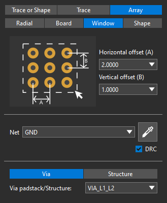
Step 17: Select Window to create a rectangular array. The widget now shows a square via array with options to set the horizontal and vertical offset.
Options are available to create an array across an entire shape, across the entire board, or to create a circular array.
Step 18: Hold the middle mouse button to pan the view over the T-shaped trace in the bottom-left corner of the board.
Step 19: Select Shapes and Nets in the Selection Filter subpanel of the Properties panel to avoid selecting the ground plane.
Step 20: Click and drag to select the trace structure.
Step 21: The outline for the via array is attached to the cursor. Move your mouse back to the first corner and click to draw the array preview.
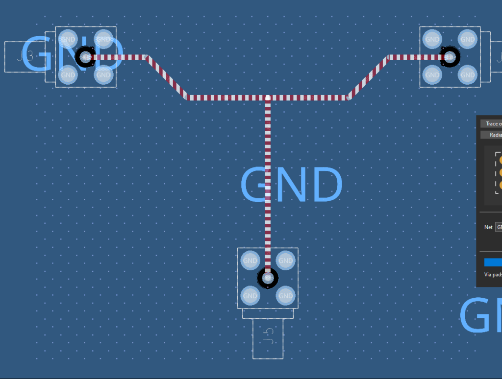
Step 22: Click again to create the rectangular via array.
Step 23: Choose the Select mode from the toolbar or press Escape on the keyboard to exit the Via Array mode.
Wrap Up & Next Steps
Quickly configure and create via arrays to accelerate your PCB layouts with OrCAD X Presto. Test out this feature and more with a free trial of OrCAD X Presto. For more how-tos and step-by-step walk-throughs, visit EMA Academy.

