When performing component placement with Allegro X AI, the schematic information and netlist are leveraged to generate the optimal placement, keeping connections short. However, there are some situations that can require additional user input, such as when multiple capacitors of varying frequency ranges are assigned to a device pin.
In this situation, a component association file can be incorporated into Allegro X AI to provide the AI engine with user-driven guidance. The component associations can be created in a spreadsheet (.csv), mapping the varying decoupling capacitors to the correct IC pin to keep the power delivery network stable.
This quick how-to will provide step-by-step instructions on how to define component associations for Allegro X AI.
To follow along, download the provided files above the table of contents.
How-To Video
 Open in New Window
Performing Component Placement with Allegro X AI
Step 1: First, we will examine component placement in Allegro X AI using the default inputs of the schematic and netlist information. Select Run X AI to start component placement.
Note: For this how-to, the workspace and design has already been configured in Allegro X AI. For help configuring the workspace for component placement, view the step-by-step instructions here.
Step 2: When placement finishes, select the Download button in the X AI panel to view the results.
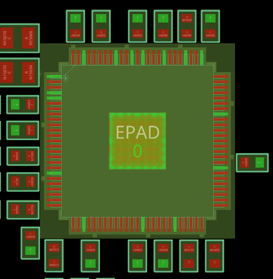
Step 3: View the results. Zoom in to view capacitor placement around U4. While the smoothing capacitors are reasonably close to pins on the same power net, some of these pins are connected to power for pullup and do not need smoothing capacitors.
Step 4: To return to the original board, select File > Open from the menu and select the board hdmi_dac.brd file in the working directory. If prompted to save changes to the new board, click No.
Creating a Component Association File
Since this design has multiple decoupling capacitors associated with an IC pin, a component association file can be created and included in the Allegro X AI setup to provide user-driven guidance.
Step 5: Component associations are defined in CSV tables. Open a spreadsheet editor such as Microsoft Excel or LibreOffice Calc.
Step 6: The component association should contain critical information for each association. Enter Net, D-Cap, Device, and Pin as the headings in the first row.
Note: This is the order in which each row of the association table must be formatted. The “Net” column does not require an input and can be left blank.
Step 7: Copy and paste the following table into the subsequent rows.
| Net | D-Cap | Device | Pin |
| +DVDD | C11 | U4 | 38 |
| +DVDD | C12 | U4 | 67 |
| +OVDD | C15 | U4 | 29 |
| +OVDD | C16 | U4 | 43 |
| +OVDD | C17 | U4 | 57 |
| +OVDD | C18 | U4 | 78 |
| +AVDD | C13 | U4 | 84 |
| +AVDD | C14 | U4 | 95 |
| +PVDD | C19 | U4 | 97 |
Step 8: Save the file in the working directory with a .csv extension. Close the spreadsheet editor.
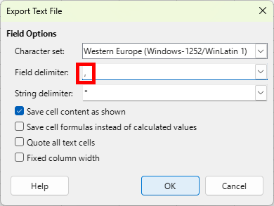
Note: Ensure the field delimiter is set to the comma (,).
Assigning Component Associations in Allegro X AI
Step 9: Back in OrCAD X, select Component Associations in the X AI workspace.
Step 10: Select Choose File under Component Associations to assign the file.
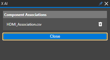
Step 11: Browse to and select the CSV file saved in the previous section. Click Open to assign the table.
Step 12: Click Close to return to the X AI workspace.
Incorporating Component Associations in Allegro X AI
Step 13: Select Run X AI to run component placement.
Step 14: When placement finishes, select the Download button in the X AI panel to view the results.
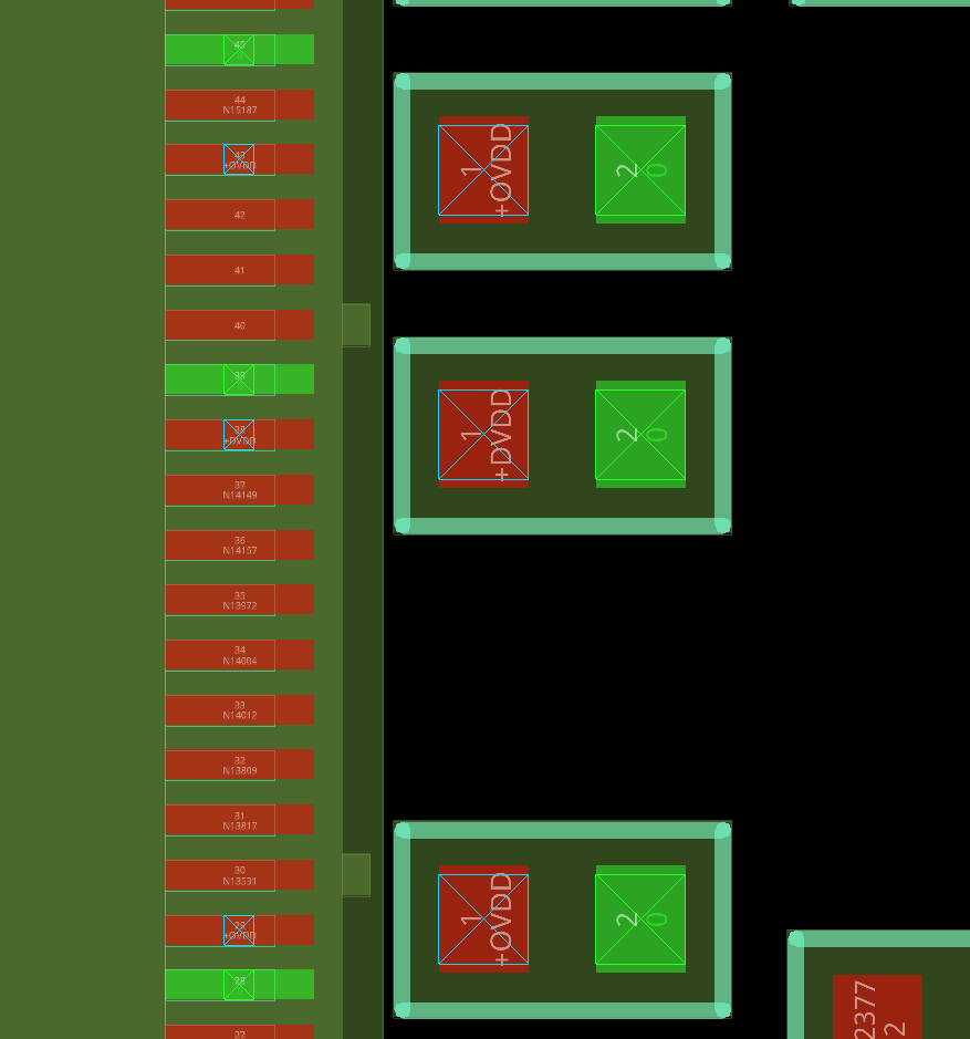
Step 15: View the capacitor placement around U4. Each pin defined in the table has a decoupling capacitor placed in an optimal location.
Wrap Up & Next Steps
Quickly and easily define component associations to improve AI-generated component placement and ensure stable power and signal integrity with Allegro X AI in OrCAD X. Learn more about X AI here
and get more how-tos for OrCAD X at EMA Academy.

