
Export Techfiles: Cross-Section
Design-specific technology files for only the cross-section can be generated from the cross-section editor. This method is suggested when a designer wants to reuse the layer stackup of the design but no other design information such as constraints, properties, manufacturing rules, etc.
Step 1: Open the provided design in OrCAD X.
Step 2: For design-specific technology files, the layer stackup is preserved in the export. To verify and export the layer stackup, select Tools > Cross Section from the menu.
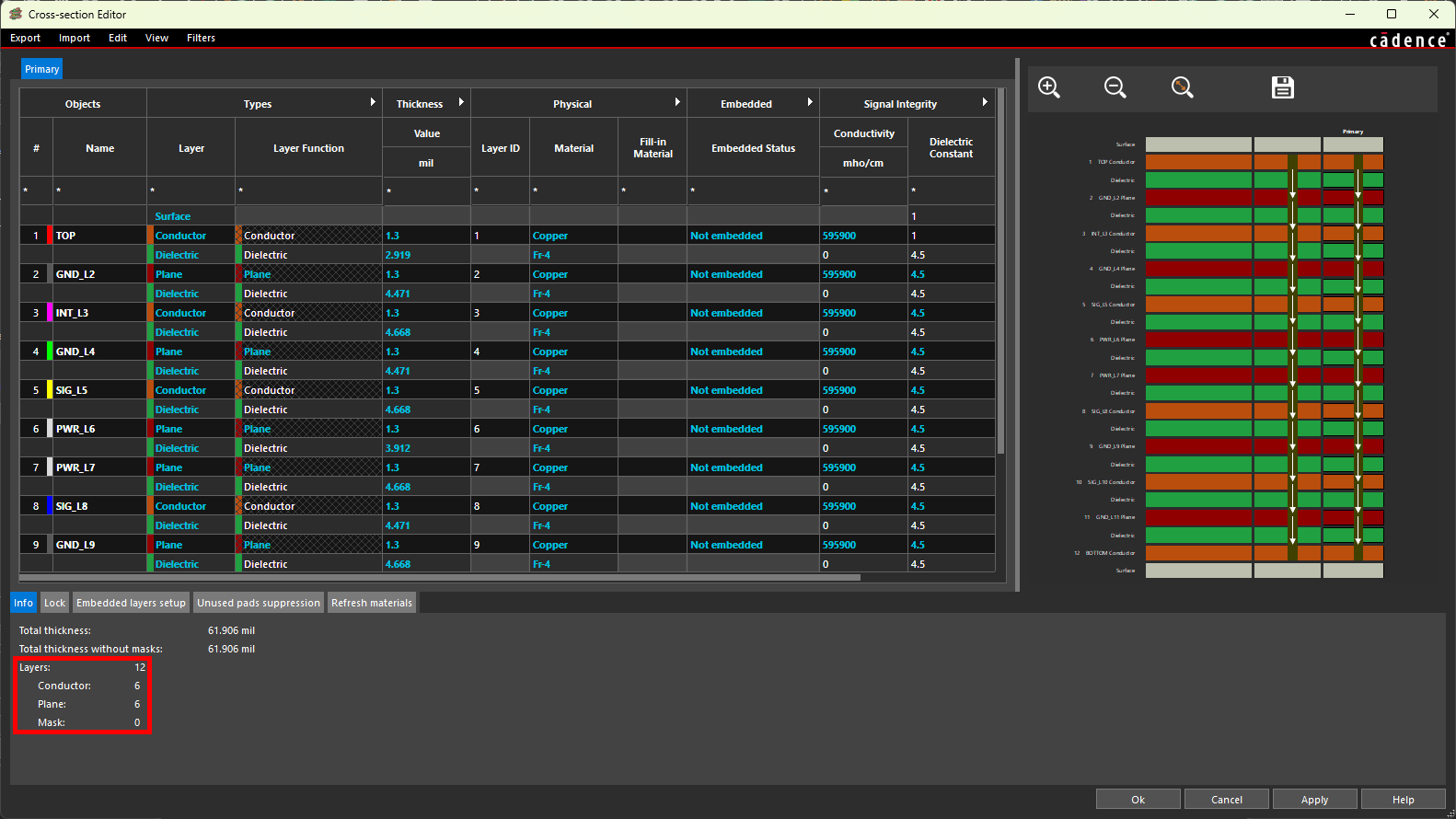
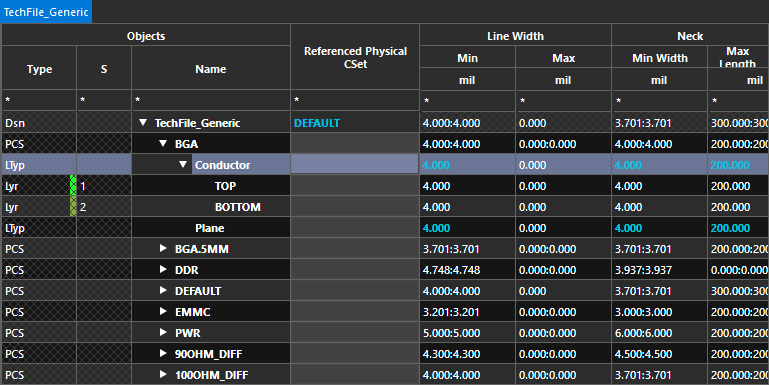
Step 3: The Cross-Section Editor opens to show a tabular representation of the board stackup. View the stackup info at the bottom of the window. Note the number of conductor and plane layers in this stackup.
Step 4: Select Export > Cross-Section Technology File from the menu.
Step 5: The Export a Cross-Section Technology File window opens. Enter a name for the technology file and click Save to save the file.
Step 6: Click OK to close the Cross-Section Editor window.
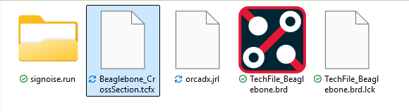
Step 7: Open File Explorer and browse to the working directory. A new file with the name defined earlier and a TCFX extension has been created.
Import Design Specific Techfiles: Cross-Section
A cross-section technology file can be imported into new designs to reuse a board stackup, saving time configuring the layers required for the PCB.
Step 8: Select File > New > Board from the menu back in Presto.
Step 9: If prompted to save the changes made to the provided board, click No.
Step 10: Select Tools > Cross Section from the menu to open the Cross-Section Editor.
Step 11: Select Import > Cross-Section Technology File from the Cross-Section Editor menu.
Step 12: A prompt appears saying that importing a techfile cannot be undone. Click Yes to proceed.
Step 13: Browse to and select the tech file. Select Overwrite under Import Mode to replace the default stackup. Click Open.
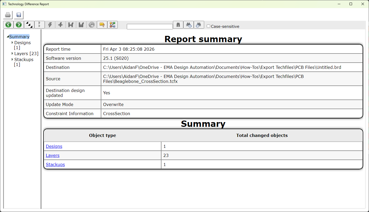
Step 14: A Technology Difference Report window opens, showing the number of layers added. View and close the report.
Step 15: View the cross section. The twelve layers from the original design have been successfully imported. Click OK to close the Cross-Section Editor.
Export Techfiles: Design-Specific Techfiles
Design-specific technology files can also be exported to include design information such as:
-
User property definitions defined in OrCAD X and added to the Constraint Manager worksheets as columns
-
Electrical constraints
-
Physical constraints
-
Spacing constraints
-
Properties
-
Manufacturing constraints
-
3D constraints
Using design-specific technology files are ideal for scenarios in which the constraints used are influenced by the layer stackup:
-
Layer-specific technology constraints
-
Requirements for differential pairs
-
Impedance requirements
-
DDR constraints
-
USB constraints
-
Inner layer thermal relief
-
Varying physical and spacing requirements per layer
-
-
Inter-layer checks for rigid-flex designs
Step 16: To reload the original board, select File > Open from the menu.
Step 17: Browse to the provided board file, select it, and click Open.
Step 18: When prompted to save the changes to the new board file, click No.
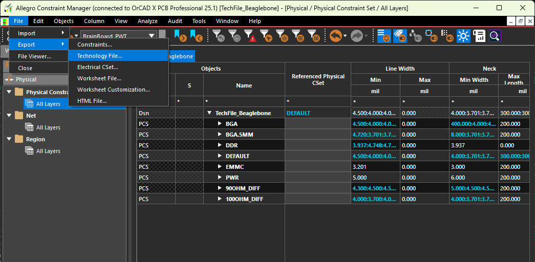
Step 19: Design-specific technology files are exported from the Constraint manager. Select Electrical Analysis > Constraint Manager from the menu.
Step 20: The Constraint Manager window opens, showing the available constraint domains and worksheets. To create a techfile, select File > Export > Technology File from the Constraint Manager menu.
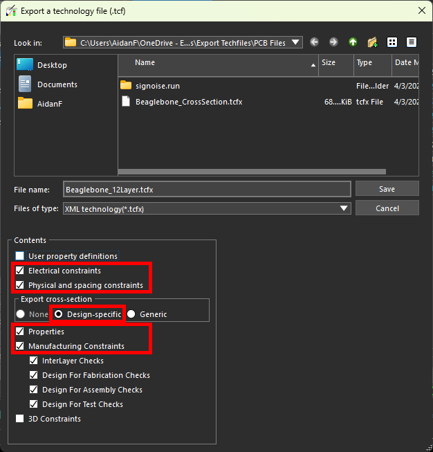
Step 21: The Export a Technology File window opens. From here, you can define which constraints and other properties to export, how to export the cross section, and where to save the tech file. Enter a name for the file in the File Name field.
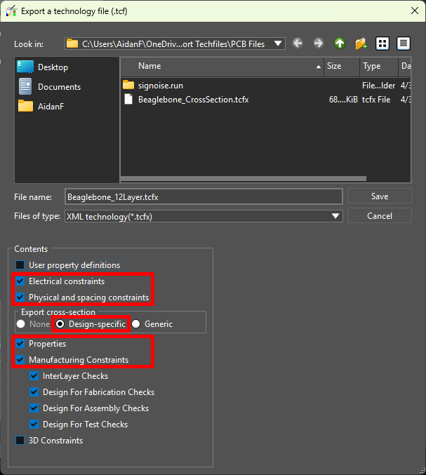
Step 22: Select Design-Specific under Export Cross-Section to export a design-specific file with the stackup.
Step 23: Check the following options:
-
Electrical Constraints
-
Physical and Spacing Constraints
-
Properties
-
Manufacturing Constraints
Step 24: Click Save to save the techfile. Close the Constraint Manager.
Import Design Specific Techfiles
Step 25: Design-specific technology files with constraints are imported through the Constraint Manager as well. Select File > New > Board from the menu to create a new board.
Step 26: When prompted to save the provided board, click No.
Step 27: Select Electrical Analysis > Constraint Manager.
Step 28: Select File > Import > Technology File from the Constraint Manager menu.
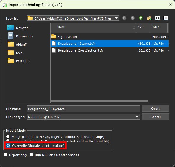
Step 29: The Import a Technology File window opens. Browse to and select the saved technology file.
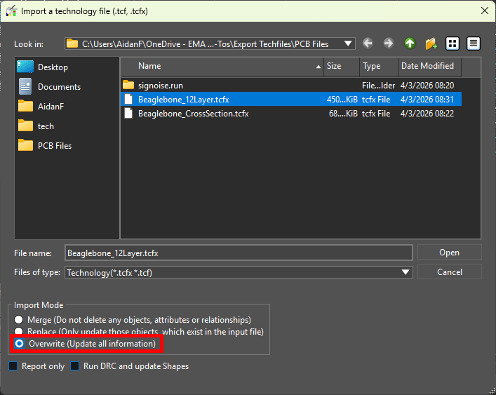
Step 30: Choose Overwrite from the Import Mode list to clear the existing constraint sets and replace them with those from the techfile.
Step 31: Click Open to import the file.
Step 32: A Technology Difference Report file opens, showing the new layers and constraints added. View and close the report.
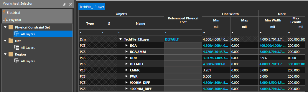
Step 33: In the Constraint Manager, select the Physical domain and select the Physical Constraint Set > All Layers worksheet. The constraints from the provided design have been imported, allowing you to quickly reuse constraints in your design and save time with setup.
Step 34: Close the Constraint Manager.
Step 35: Select Tools > Cross Section from the menu.
Step 36: The Cross-Section Editor window opens. The twelve layers from the provided board were imported successfully as well. Click OK to close the Cross-Section Editor.
Export Techfiles: Generic Techfiles
Generic techfiles contain only the constraint sets defined for a board but do not include the layer assignments or stackup. Generic techfiles should be used when greater control is needed over the export such as reusing specific constraints instead of the entire configuration. Generic technology files are ideal for:
-
Reusing manufacturing constraints that are not layer-specific
-
Design for fabrication requirements
-
Design for assembly (DFA) requirements
-
Design for test (DFT) requirements
-
Physical and spacing rules to accommodate specific manufacturer capabilities
-
-
Reusing technology-specific constraints that are not layer-specific
-
Power and ground net constraints
-
Trace type thicknesses (for example, signal, low power, high power, etc.)
-
Conductor and feature spacing
-
Via and hole diameter
-
Step 37: Select File > Open from the menu to reopen the provided board.
Step 38: Select the provided board file and click Open.
Step 39: When prompted to save the new board, click No.
Step 40: The original board file reopens. Generic technology files must be exported from the Constraint Manager. Select Electrical Analysis > Constraint Manager from the menu.
Step 41: Select File > Export > Technology File from the Constraint Manager menu.
Step 42: The Export a Technology File window opens. Enter a name for the file in the File Name field.
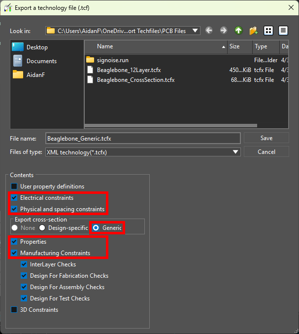
Step 43: Select Generic under Export Cross-Section to export a generic file with no stackup.
Step 44: Check the following options:
-
Electrical Constraints
-
Physical and Spacing Constraints
-
Properties
-
Manufacturing Constraints
Step 45: Click Save to save the techfile. Close the Constraint Manager.
Import Generic Techfiles
Generic techfiles can be imported into new designs to auto-populate constraint sets, allowing designers to quickly reuse rules and save time with design configuration. After import, these constraint sets must then be assigned to layers and nets and the design.
Step 46: Select File > New > Board from the menu. If prompted to save the changes made to the provided board, click No.
Step 47: Select Electrical Analysis > Constraint Manager from the menu to activate the Constraint Manager.
Step 48: Select File > Import > Technology File from the menu.
Step 49: The Import a Technology File window opens. Select the previously-saved generic techfile.
Configuring a Techfile Import
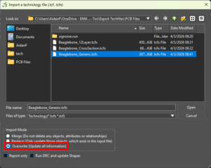
Step 50: Choose Overwrite from the Import Mode list to clear the existing constraint sets and replace them with those from the techfile.
Step 51: Select Open to import the tech file. The window closes automatically.
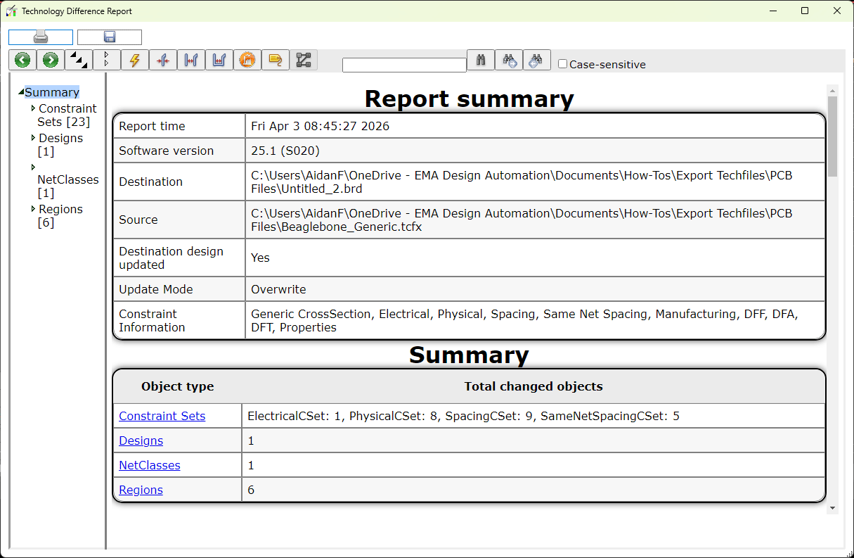
Step 52: A Technology Difference Report window opens, showing a log of the imported constraint sets. View and close the report.
Step 53: View the Physical Constraint Set > All Layers worksheet in the Constraint Manager. All constraints from the original design have been imported.
Step 54: Select the arrow to expand a constraint set to see the available layers. Only two layers are listed, as is the default with a new board. These constraints can now be assigned to nets in the design.
Export Techfiles: Cross-Section
Design-specific technology files for only the cross-section can be generated from the cross-section editor. This method is suggested when a designer wants to reuse the layer stackup of the design but no other design information such as constraints, properties, manufacturing rules, etc.
Step 1: Open the provided design in OrCAD X.
Step 2: For design-specific technology files, the layer stackup is preserved in the export. To verify and export the layer stackup, select Setup > Cross-Section from the menu.
Step 3: The Cross-Section Editor opens to show a tabular representation of the board stackup. View the stackup info at the bottom of the window. Note the number of conductor and plane layers in this stackup.
Step 4: Select Export > Cross-Section Technology File from the menu.
Step 5: The Export a Cross-Section Technology File window opens. Enter a name for the technology file and click Save to save the file.
Step 6: Click OK to close the Cross-Section Editor window.
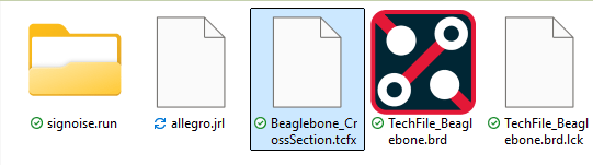
Step 7: Open File Explorer and browse to the working directory. A new file with the name defined earlier and a TCFX extension has been created.
Import Design Specific Techfiles: Cross-Section
A cross-section technology file can be imported into new designs to reuse a board stackup, saving time configuring the layers required for the PCB. For this example, a blank board will be used.
Step 8: Select File > New from the menu back in PCB Designer.
Step 9: If prompted to save the changes made to the provided board, click No.
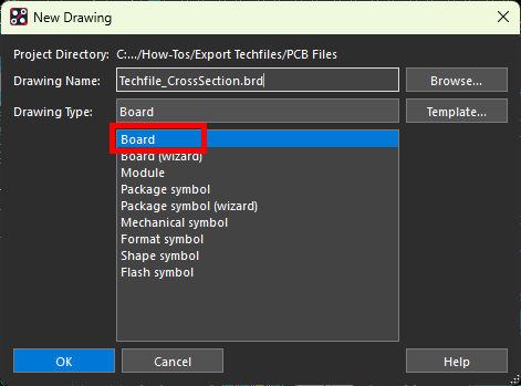
Step 10: The New Drawing window opens. Select Board for the drawing type.
Step 11: Click Browse to open the file browser for the new board. Browse to the working directory, enter a name for the board, and click Open.
Step 12: Click OK to create the board.
Step 13: The Create a New Design Window opens. Here you can configure board units, dimensions, and accuracy. Leave the default settings and click OK to generate the blank canvas.
Step 14: Select Setup > Cross-Section from the menu to open the Cross-Section Editor.
Step 15: Select Import > Cross-Section Technology File from the Cross-Section Editor menu.
Step 16: A prompt appears saying that importing a techfile cannot be undone. Click Yes to proceed.
Step 17: Browse to and select the tech file. Select Overwrite under Import Mode to replace the default stackup. Click Open.
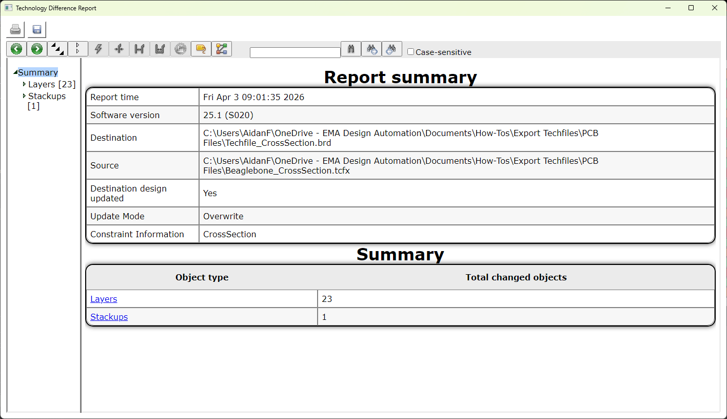
Step 18: A Technology Difference Report window opens, showing the number of layers added. View and close the report.
Step 19: View the cross section. The twelve layers from the original design have been successfully imported. Click OK to close the Cross-Section Editor.
Export Techfiles: Design-Specific Techfiles
Design-specific technology files can also be exported to include additional design information such as:
-
User property definitions defined in OrCAD X and added to the Constraint Manager worksheets as columns
-
Electrical constraints
-
Physical constraints
-
Spacing constraints
-
Properties
-
Manufacturing constraints
-
3D constraints
Using design-specific technology files are ideal for scenarios in which the constraints used are influenced by the layer stackup:
-
Layer-specific technology constraints
-
Requirements for differential pairs
-
Impedance requirements
-
DDR constraints
-
USB constraints
-
Inner layer thermal relief
-
Varying physical and spacing requirements per layer
-
-
Inter-layer checks for rigid-flex designs
Step 20: To reload the original board, select File > Open from the menu.
Step 21: When prompted to save the changes to the new board file, click No.
Step 22: Browse to the provided board file, select it, and click Open.
Step 23: Design-specific technology files are exported from the Constraint manager. Select Setup > Constraints from the menu.
Step 24: The Constraint Manager window opens, showing the available constraint domains and worksheets. To create a techfile, select File > Export > Technology File from the Constraint Manager menu.
Step 25: The Export a Technology File window opens. From here, you can define which constraints and other properties to export, how to export the cross section, and where to save the tech file. Enter a name for the file in the File Name field.
Step 26: Select Design-Specific under Export Cross-Section to export a design-specific file with the stackup.
Step 27: Check the following options:
-
Electrical Constraints
-
Physical and Spacing Constraints
-
Properties
-
Manufacturing Constraints
Step 28: Click Save to save the techfile. Close the Constraint Manager.
Import Design Specific Techfiles
Step 29: Select File > New from the menu.
Step 30: If prompted to save the changes made to the provided board, click No.
Step 31: The New Drawing window opens. Select Board for the drawing type.
Step 32: Click Browse to open the file browser for the new board. Browse to the working directory, enter a name for the board, and click Open.
Step 33: Click OK to create the board.
Step 34: The Create a New Design Window opens. Leave the default settings and click OK to generate the blank canvas.
Step 35: Select Setup > Constraints.
Step 36: Select File > Import > Technology File from the Constraint Manager menu.
Step 37: The Import a Technology File window opens. Browse to and select the saved technology file.
Step 38: Choose Overwrite from the Import Mode list to clear the existing constraint sets and replace them with those from the techfile.
Step 39: Click Open to import the file.
Step 40: A Technology Difference Report file opens, showing the new layers and constraints added. View and close the report.
Step 41: In the Constraint Manager, select the Physical domain and select the Physical Constraint Set > All Layers worksheet. The constraints from the provided design have been imported, allowing you to quickly reuse constraints in your design and save time with setup.
Step 42: Close the Constraint Manager.
Step 43: Select Setup > Cross-Section from the menu.
Step 44: The Cross-Section Editor window opens. The twelve layers from the provided board were imported successfully as well. Click OK to close the Cross-Section Editor.
Export Techfiles: Generic Techfiles
Generic techfiles contain only the constraint sets defined for a board, not the layer assignments or stackup. Generic techfiles should be used when greater control is needed over the export such as reusing specific constraints instead of the entire configuration. Generic technology files are ideal for:
-
Reusing manufacturing constraints that are not layer-specific
-
Design for fabrication requirements
-
Design for assembly (DFA) requirements
-
Design for test (DFT) requirements
-
Physical and spacing rules to accommodate specific manufacturer capabilities
-
-
Reusing technology-specific constraints that are not layer-specific
-
Power and ground net constraints
-
Trace type thicknesses (for example, signal, low power, high power, etc.)
-
Conductor and feature spacing
-
Via and hole diameter
-
Step 45: Select File > Open from the menu to reopen the provided board.
Step 46: When prompted to save the new board, click No.
Step 47: Select the provided board file and click Open.
Step 48: The original board file reopens. Generic technology files must be exported from the Constraint Manager. Select Setup > Constraints from the menu.
Step 49: Select File > Export > Technology File from the Constraint Manager menu.
Step 50: The Export a Technology File window opens. Enter a name for the file in the File Name field.
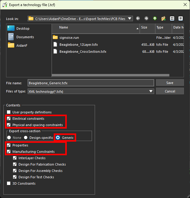
Step 51: Select Generic under Export Cross-Section to export a generic file with no stackup.
Step 52: Check the following options:
-
Electrical Constraints
-
Physical and Spacing Constraints
-
Properties
-
Manufacturing Constraints
Step 53: Click Save to save the techfile. Close the Constraint Manager.
Import Generic Techfiles
Generic techfiles can be imported into new designs to auto-populate constraint sets, allowing designers to quickly reuse rules and save time with design configuration. After import, these constraint sets must then be assigned to layers and nets and the design.
Step 54: Select File > New from the menu.
Step 55: If prompted to save the changes made to the provided board, click No.
Step 56: The New Drawing window opens. Select Board for the drawing type.
Step 57: Click Browse to open the file browser for the new board. Browse to the working directory, enter a name for the board, and click Open.
Step 58: Click OK to create the board.
Step 59: The Create a New Design Window opens. Leave the default settings and click OK to generate the blank canvas.
Step 60: Select Setup > Constraints from the menu to activate the Constraint Manager.
Step 61: Select File > Import > Technology File from the menu.
Step 62: The Import a Technology File window opens. Select the previously-saved generic techfile.
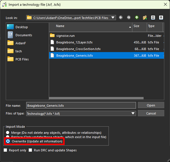
Step 63: Choose Overwrite from the Import Mode list to clear the existing constraint sets and replace them with those from the techfile.
Step 64: Select Open to import the tech file. The window closes automatically.
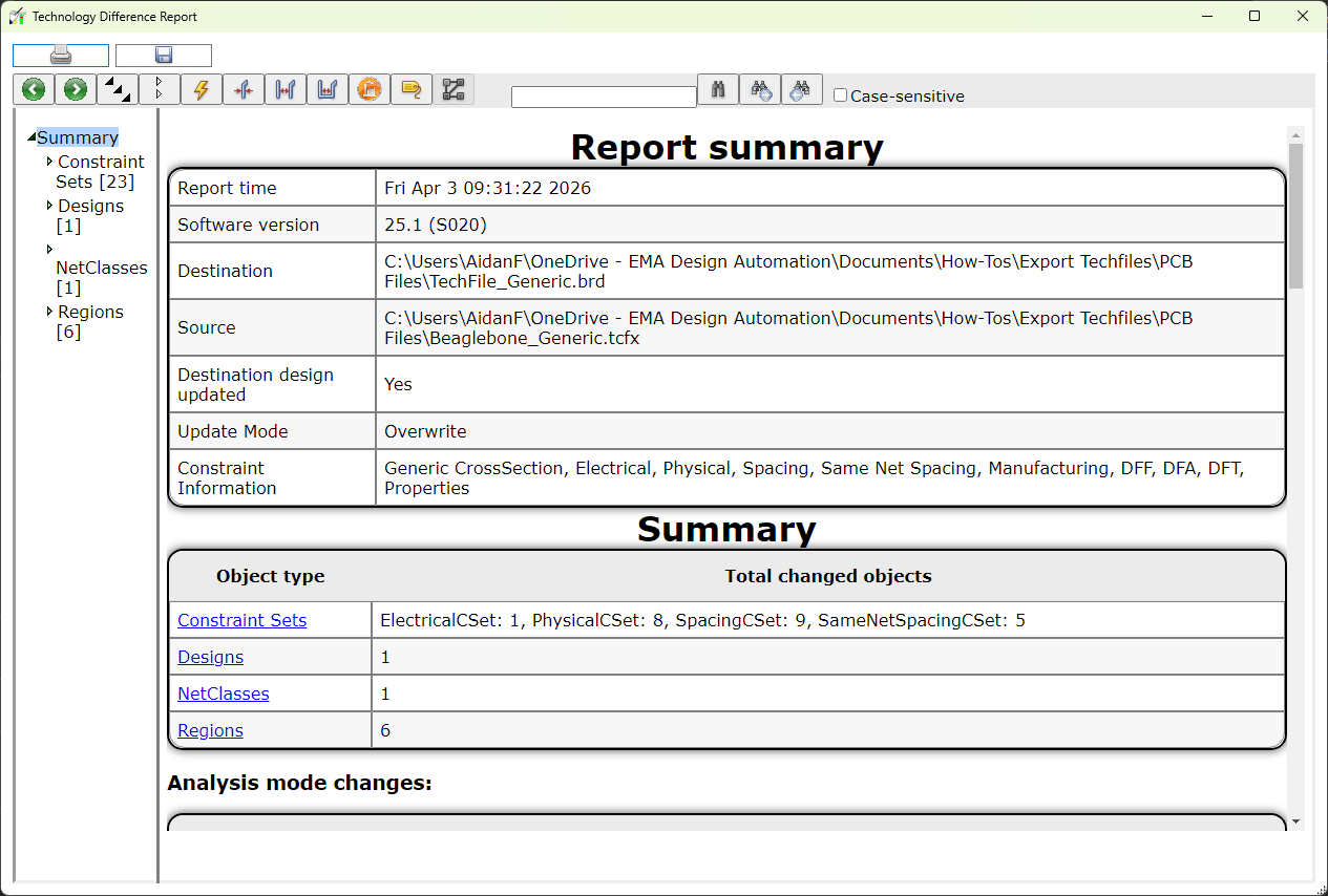
Step 65: A Technology Difference Report window opens, showing a log of the imported constraint sets. View and close the report.
Step 66: View the Physical Constraint Set > All Layers worksheet in the Constraint Manager. All constraints from the original design have been imported.

