To improve manufacturing yield, design for manufacturing (DFM) must be considered during the PCB layout. Every manufacturer has different requirements that must be adhered to including pad size and specific rules for soldermask and pastemask. Incorrect mask size can lead to a number of issues, such as incomplete solder joints and even bridges; however, with differing requirements for each manufacturer, accommodating various masks for pads in the design can be difficult. Quickly create oversized masks while preserving the original padstack with the Mask Generator in Allegro Productivity Toolbox. With Mask Generator, users can:
- Generate custom masks from pin and vias
- Specify negative and positive expansion values
- Generate masks from existing pad shapes and attributes (etch, soldermask, pastemask, and drill)
- Support variant specific masks
- Preserve original padstack definitions
- Define multiple mask options to store in the database
This quick how-to will provide step-by-step instructions on how to use the Mask Generator in Allegro Productivity Toolbox to generate oversized masks and adhere to manufacturing requirements.
To follow along, use the provided design above the table of contents.
How-To Video
Generating Masks
Step 1: Open the provided design in OrCAD PCB Designer Professional with the Allegro Productivity Toolbox option selected.
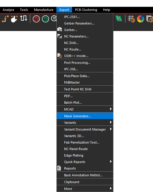
Step 2: Select Export > Mask Generator from the menu. The Mask Generator window opens.
Step 3: Select Generate to create mask layers.
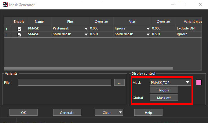
Note: When generation is complete, the Display Control pane will show the name and color of the new mask layer.
Step 4: Click OK to close the Mask Generator.
Activating Mask Layer Visibility
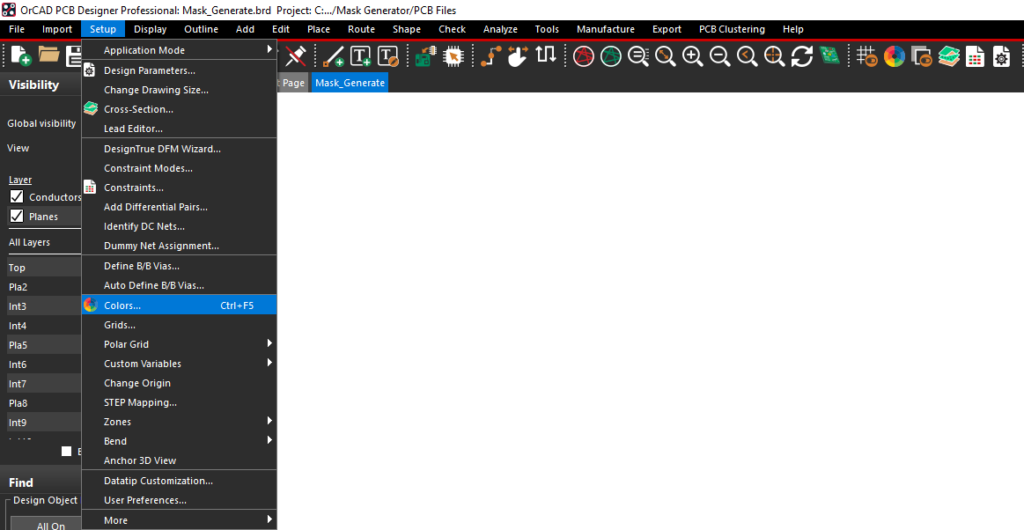
Step 5: Select Setup > Colors from the menu or the Color192 icon from the toolbar.
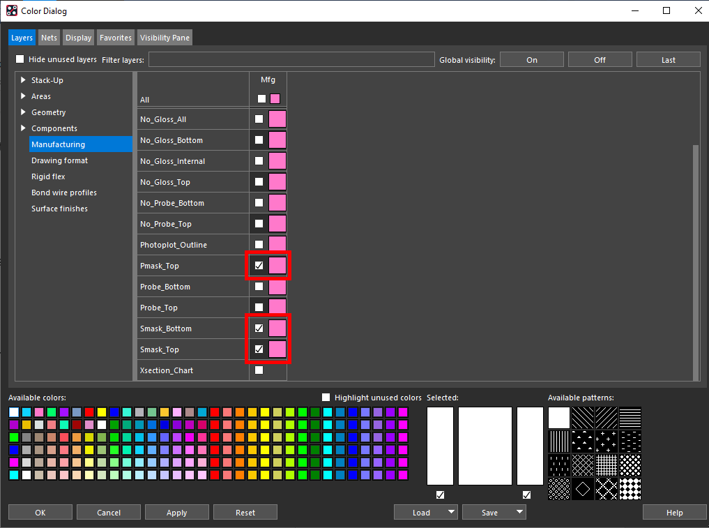
Step 6: Select the Manufacturing layer set from the side panel.
Step 7: Activate the visibility for the layers Pmask_Top, Smask_Bottom, and Smask_Top.
Step 8: Click OK to save the settings and close the Color Dialog window.
Creating Oversized Masks
Step 9: Select Export > Mask Generator from the menu.
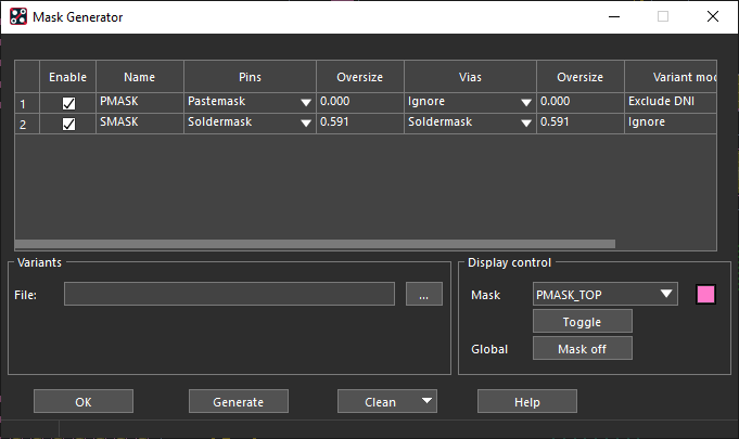
Step 10: For row 1, PMASK, set Pins to Pastemask and Vias to Ignore.
Note: If additional pad data needs to be processed, right-click and select Add Row. If pad data needs to be removed from processing, right-click and select Delete Row.
Step 11: For row 2, SMASK, set Pins to Soldermask and Vias to Soldermask.
Note: The following options are available for processing pad data:
- Ignore: This willnot generate a particular oversize mask.
- Soldermask
- Pastemask
- Etch
- Drill: This option is only available for vias in the design.
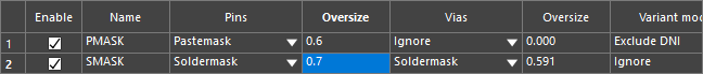
Step 11: For the pin pastemask, set the oversize to 0.6.
Note: In this example, the newly-generated mask will overlap the existing pastemask by 0.6 design units; in this case, mils.
Step 12: Set the pin soldermask oversize to 0.7.
Step 13: Leave the remaining values as the defaults and select Generate. When generation is complete, click OK to close the Mask Generator.
Note: Variant modes can be specified for masks with special requirements. For example, some manufacturers may require you to omit the paste for components which are not assembled in the current variant (DNI components).
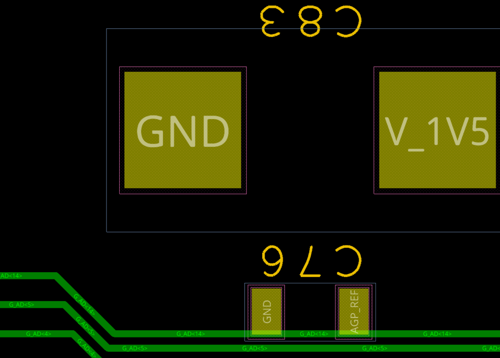
Step 14: Zoom into a component to see the oversize soldermask and pastemask.
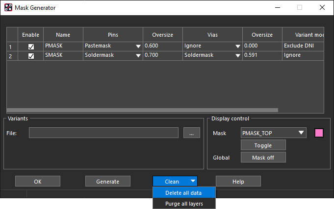
Note: To remove oversize masks, select Clean > Delete All Data.
Wrap Up & Next Steps
Quickly create oversized masks to adhere to manufacturing requirements and improve yield with the Mask Generator in Allegro Productivity Toolbox. To learn more about how the features of Allegro Productivity Toolbox can expedite your PCB designs, view our latest webinar.

