Analyzing designs for signal and power integrity is crucial to ensure first-pass success; however, with outsourcing PCB design becoming more common, CAD formats can vary making communication between tools and analysis cumbersome. Easily import designs in Sigrity and obtain a unified environment for comprehensive SI, PI, thermal, and compliance analysis regardless of CAD format.
This how-to will provide step-by-step instructions on how to import IPC-2581 file format into Sigrity for signal and power integrity analysis. This process can be completed for any of the file format Sigrity accepts.
To follow along with this tutorial, use the designs provided above the table of contents.
How-To Video
Opening Sigrity
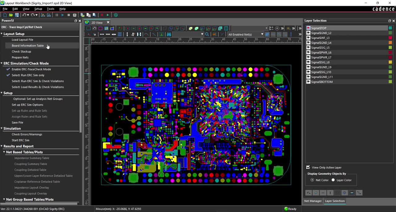
Step 1: Open the ERC- Trace Imp/Cpl/Ref Check Workflow in Sigrity.
Note: This import process can be completed for any Sigrity workflows. There may be a slight variation of step titles and locations depending on the workflow selected.
Importing an IPC-2581 File
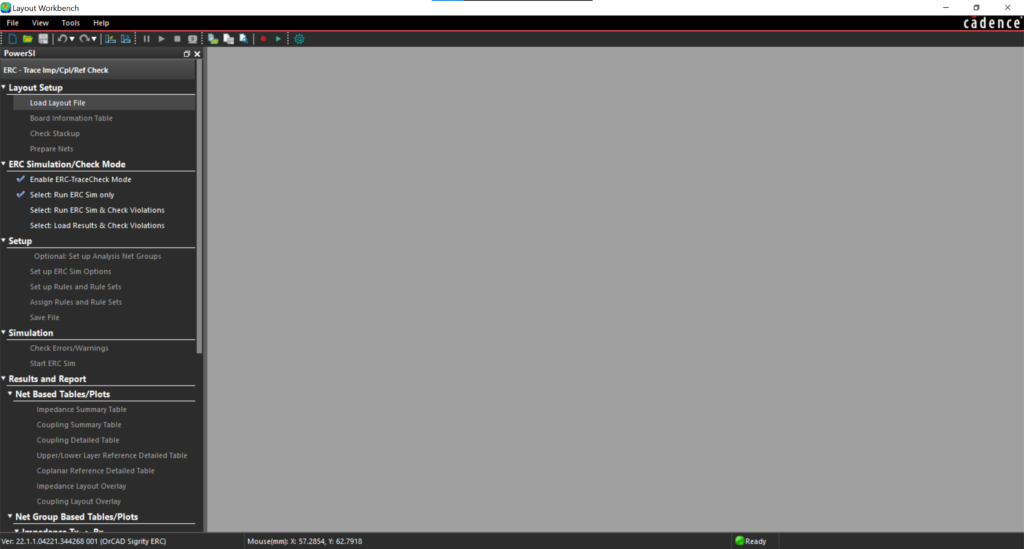
Step 2: Under Layout Setup in the workflow panel, select Load Layout File.
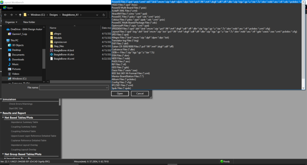
Step 3: Next to File Name, expand the selection filter for the type of file.
Note: This will display all the file types Sigrity accepts including Mentor, Altium, Zuken, Allegro, PADS, ODB++, and more.
Step 4: Select IPC2581 Files (*.xml).
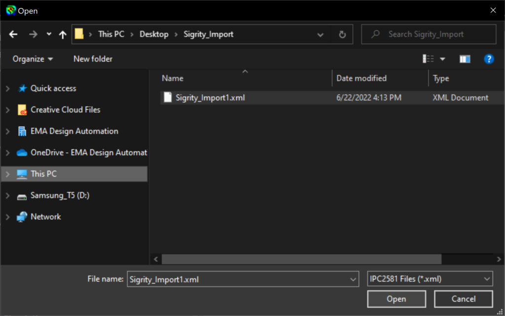
Step 5: Browse to the location of the downloaded materials and select Sigrity_Import1.xml. Click Open.
Note: During the import, the status bar will report the progress of the import and display the software status as Busy. When the import is complete, the software status will be displayed as Ready.
Verifying the Board Information
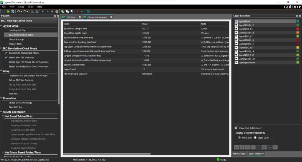
Step 6: Under Layout Setup in the workflow panel, select Board Information Table.
Note: The general board information is displayed in the Board Information Window including the board dimensions, area dimensions for component placement, layer count, and more.
Step 7: Close out of the Board Information Table.
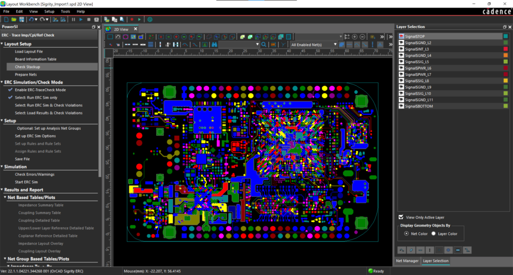
Step 8: Under Layout Setup in the workflow panel, select Check Stackup.
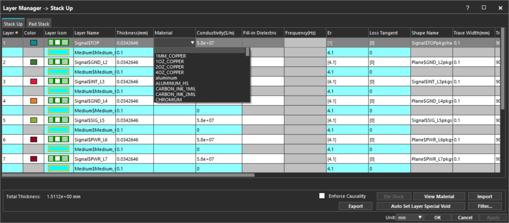
Step 9: Verify the board stack up has been imported correctly.
Note: For this example, the stackup has imported correctly. Conductivity, material, thickness and more can be modified during any import to create a more accurate simulation.
Step 10: Close out of the Stackup Window.
Preparing the Design for Simulation
Step 11: Under Layout Setup in the workflow panel, select Prepare Nets.
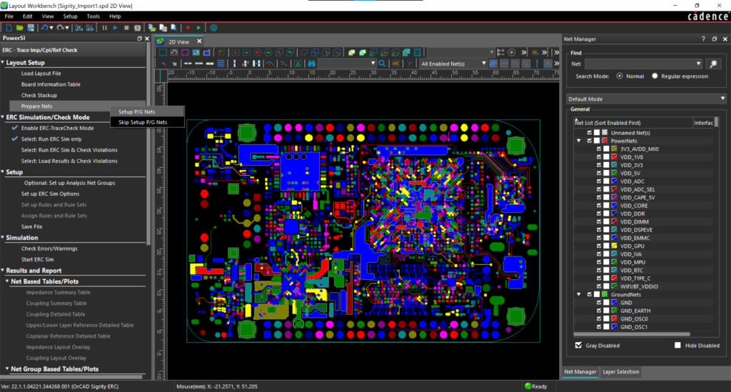
Step 12: From the pop-up menu, select Setup P/G Nets.
Step 13: From the P/G Net Classification Wizard, select the desired components by checking the corresponding box. Click Next.
Note: The classification wizard automatically detects the potential power and ground nets in the design.
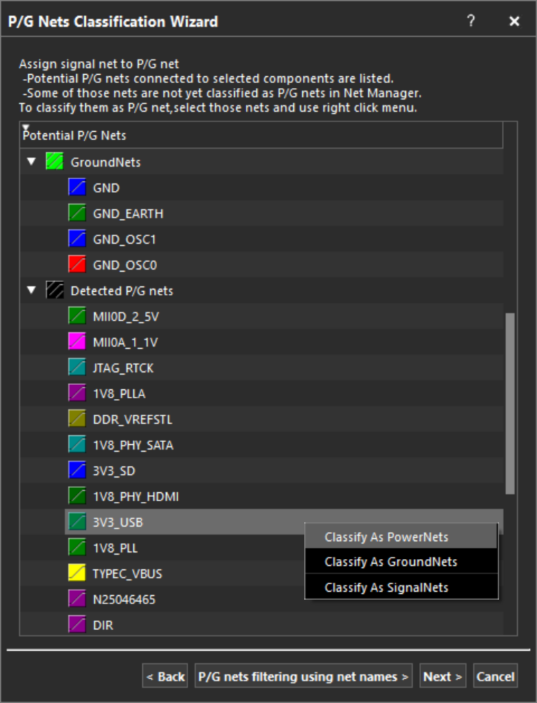
Step 14: Review the nets categorized as Detected P/G Nets. Right click on a net and select Classify as Powernets, Classify as Groundnets, or Classify as SignalNets.
Step 15: Complete this process for the Detected P/G Nets and click Next.
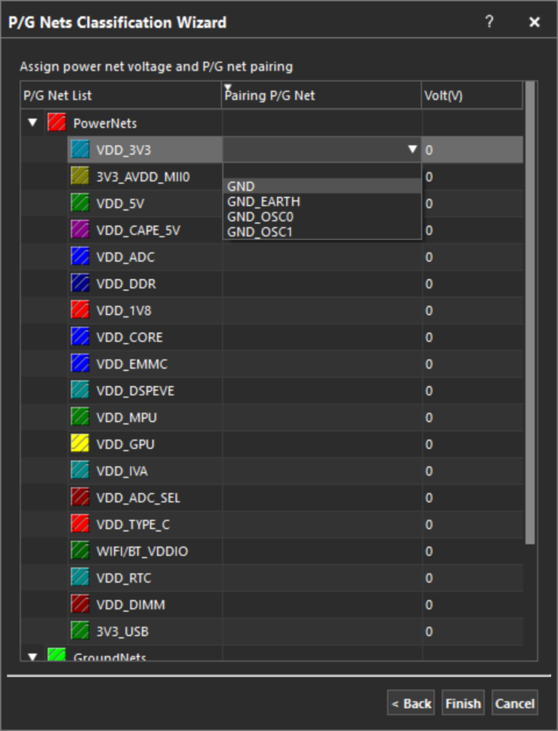
Step 16: Under Pairing P/G Net, select the cell for the desired net. Select the arrow and choose the appropriate ground net.
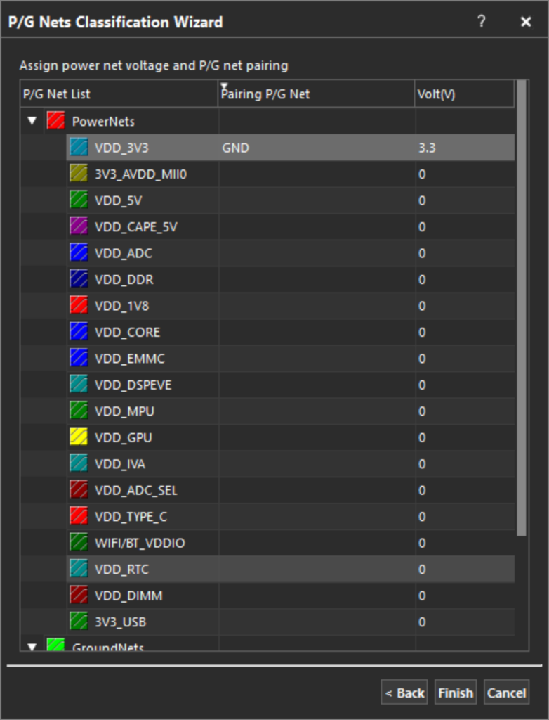
Step 17: In the Volt (V) column, assign the appropriate voltage value for the net.
Step 18: Complete this process for the power and ground nets in the design.
Step 19: Select Finish.
Note: With the design imported and setup, the remainder of the workflow can be completed to perform the desired analysis.
Wrap Up & Next Steps
With the increasing complexity and speed of today’s designs, it’s essential to analyze signal integrity, power integrity, and compliance to guarantee a successful product. Import designs in Sigrity to perform comprehensive analysis on high-speed PCBs regardless of CAD or file format. See how Sigrity can solve SI and PI problems early in the PCB design process with our free webinar.

