For circuits such as volume controls, light dimmers, and variable power supplies, the potentiometer becomes an indispensable component. Most modern SPICE software has at least variable resistor models available. While it is possible to simulate the effect of a potentiometer by sweeping the values of two resistors, this can be quite tedious to set up if both sides of the potentiometer resistor are connected. PSpice includes a versatile potentiometer model that can be used for value sweeps, parametric analysis, and more.
This quick how-to will provide step-by-step instructions on how model a potentiometer in PSpice for quick and accurate simulations.
To follow along, download the provided files above the table of contents.
How-To Video
 Open in New Window
Model a Potentiometer in PSpice
Step 1: Open the provided design in PSpice Designer.
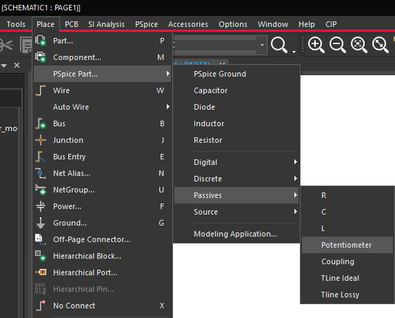
Step 2: Select Place > PSpice Part > Passives > Potentiometer from the menu.
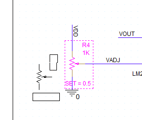
Step 3: Click to place the potentiometer in the empty space in the schematic with VADJ connected to the wiper. Right-click and select End Mode.
Note: Press R on the keyboard to rotate as needed. The potentiometer is placed but the wiper position is fixed.
Step 4: Right-click the potentiometer model and select Edit PSpice Model to view the associated SPICE code.
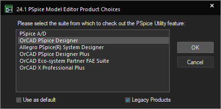
Note: If the PSpice Model Editor Product Choices window opens, select the appropriate license and click OK.
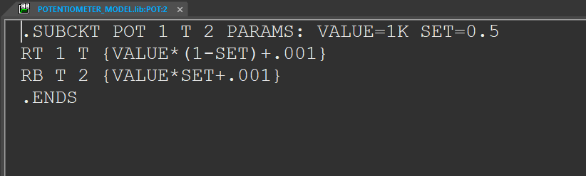
Step 5: The PSpice Model Editor opens to show the SPICE code for the potentiometer model. The code defines a three-terminal circuit with parameters VALUE and SET. Two resistance formulas are shown as functions of the value and setting. These formulas add 0.001 to each resistance value to prevent direct shorts when the setting is at 1 or 0.
Close the PSpice Model Editor.
Model a Potentiometer: Defining a Variable Value
Note: Several methods exist to analyze a potentiometer circuit at multiple values. The following method will repeat a transient simulation for a pre-defined set of values.
Step 6: Double-click the SET parameter on the potentiometer to change it.
Step 7: In the Display Properties window, enter {RSET} for the value and click OK.
Note: This will assign the potentiometer setting to a global design parameter.
Step 8: To place the design parameter list, select Place > Component from the menu.
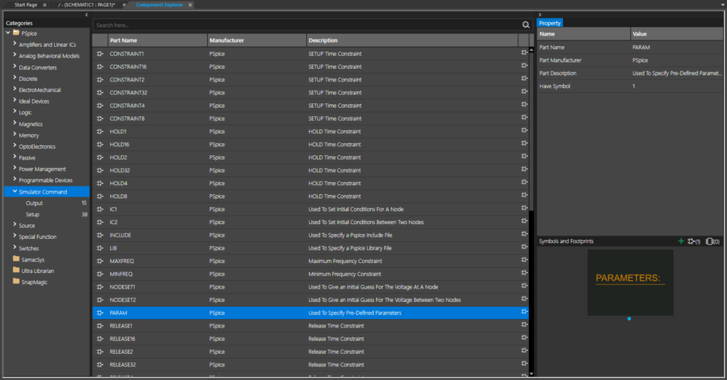
Step 9: The Component Explorer tab opens. Expand the PSpice folder in the Categories list and select Simulator Command > Setup.
Step 10: Select the PARAM component. This is a list object used to specify design parameters to model a potentiometer in the schematic canvas. Double-click to attach the component to your cursor.
Step 11: Click to place the PARAM component on the schematic canvas. Right-click and select End Mode.
Model a Potentiometer: Defining the Value Property
Step 12: Double-click the Parameters object to open the Property Editor tab.
Step 13: The Property Editor tab opens to show a table of all properties defined for the Parameters object. Global design parameters are defined as properties here. Select New Property to create a new property.
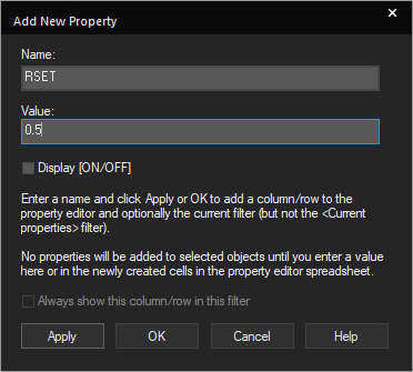
Step 14: Enter RSET for the name and 0.5 for the value in the Add New Property window.
Step 15: Check the option for Display [ON/OFF] to allow the parameter to be displayed on the schematic canvas. Click OK.
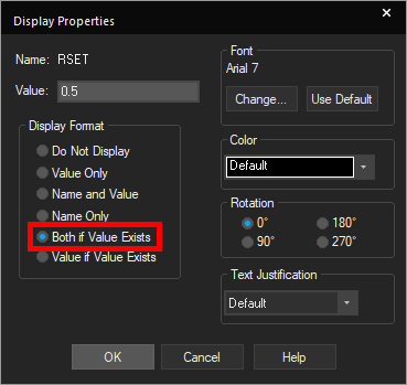
Step 16: The Display Properties window opens. Here you can define how the parameter is displayed. Select Both if Value Exists to display the parameter name and value on the canvas. Click OK.
Step 17: Click Apply and close the Property Editor tab. The RSET property is shown in the Parameters list in the schematic canvas.
Running a Multi Parameter Simulation
Step 18: To create a new simulation profile, select PSpice > New Simulation Profile from the menu.
Step 19: Name the simulation POTENTIOMETER_TRANS and click Create.
Note: If the Simulation Manager Product Choices window opens, select the appropriate license and click OK.
Step 20: The Simulation Settings window opens. Enter 200ms for the Run To Time and 50us for the Maximum Step Size.
Step 21: Check the option for Parametric Sweep.
Step 22: In the Sweep Variable subpanel, select Global Parameter as the variable. Enter RSET for the Parameter Name.
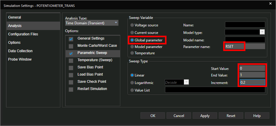
Step 23: Set the Sweep Type to Linear, enter 0 for the Start Value, 1 for the End Value, and 0.2 for the Increment.
Click OK to save the settings and close the window.
Step 24: Probes must be placed on the schematic for simulation results to show. Select the Voltage/Level Marker button from the toolbar to place a probe.
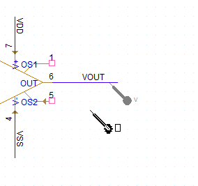
Step 25: Click to place a probe on the VOUT net. Right-click and select End Mode.
Step 26: Select PSpice > Run from the menu to start the simulation.
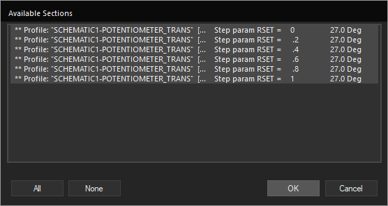
Step 27: When the simulation finishes, the PSpice A/D window opens to the Available Sections window. Here you can define which parameter values are plotted. Select All and click OK.
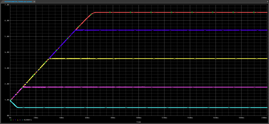
Step 28: View the simulation results. A transient plot is shown for each potentiometer state.
Running a Potentiometer Sweep
Note: A DC sweep simulation can be used to sweep all values of the potentiometer and plot the steady-state result voltage.
Step 29: Close the PSpice A/D window.
Step 30: Back in Capture, select PSpice > New Simulation Profile from the menu.
Step 31: Name the profile POTENTIOMETER_DC and click Create.
Step 32: In the Simulation Settings window, select DC Sweep from the Analysis Type dropdown.
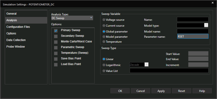
Step 33: Select Global Parameter for the Sweep Variable and enter RSET for the Parameter Name.
Step 34: Select Linear for the Sweep Type. Enter 0 for the Start Value, 1 for the End Value, and 0.1 for the Increment.
Step 35: Select Options from the list on the left.
Note: Since VOUT oscillates in this design, autoconvergence must be enabled for the steady-state simulation to work.
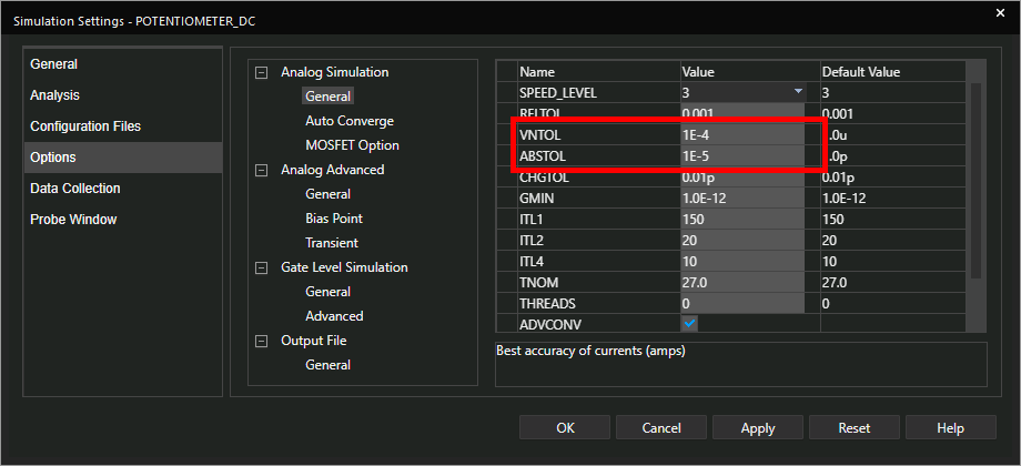
Step 36: The Analog Simulation settings table opens. Set VNTOL to 1E-4 and ABSTOL to 1E-5 for faster convergence.
Step 37: Select Analog Simulation > Auto Converge from the side panel.
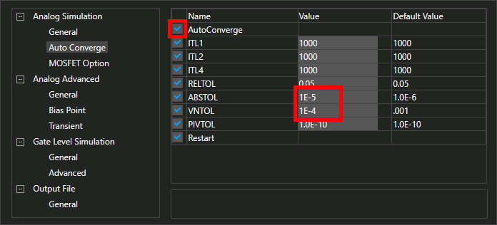
Step 38: Check the option for AutoConverge. Set the initial ABSTOL to 1E-5 and VNTOL to 1E-4.
Click OK to save the settings and close the window.
Step 39: Select the Voltage/Level Marker button from the toolbar.
Note: Since this is a new simulation profile, probes must be defined again.
Step 40: Click to place a probe on the VOUT net. Right-click and select End Mode.
Step 41: Select PSpice > Run from the menu.
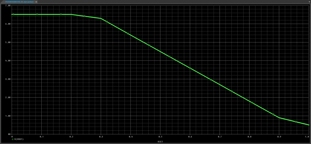
Step 42: View the simulation results. The output voltage decreases as the potentiometer value increases. The wiper gets closer to ground as the value increases.
Wrap Up & Next Steps
Quickly model a potentiometer for quick and accurate circuit analysis with PSpice Designer. Test out this feature and more with a free trial of OrCAD. Want to learn more about PSpice? View additional how-tos, walk-throughs, and courses at EMA Academy.

