Having accurate component models is critical to ensure an accurate simulation. While many magnetic parts, such as flyback transformers and ferrite beads, have SPICE models available for downloaded, often customization is required. Easily model magnetic parts in PSpice Designer to quickly create custom magnetic parts to accurately simulate circuit functionality.
This quick how-to will provide step-by-step instructions on how to create magnetic parts, such as flyback transformers, in PSpice Designer.
To follow along, download the provided files above the table of contents.
How-To Video
 Open in New Window
Modeling Transformer Coils
Step 1: Open the provided design in PSpice Designer.
Step 2: Select Place > PSpice Part > Inductor from the menu.
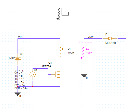
Step 3: Click to place two inductors in the empty spaces in the design. Ensure they are oriented as shown. Right-click and select End Mode.
Note: Press R on the keyboard to rotate a component as needed.
Step 4: Double-click the value of the primary inductor on the left to change it.
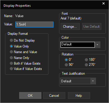
Step 5: The Display Properties window opens. This example will model the Würth Elektronik 7508110151 transformer, whose primary inductance is 1.5mH. Enter 1.5mH for the value and click OK.
Step 6: Double-click the value for the secondary inductor to change it.
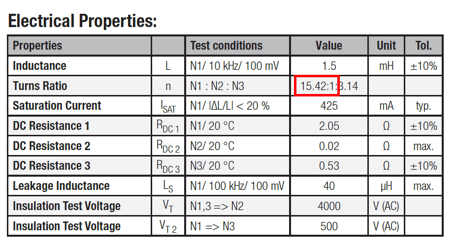
Step 7: According to the transformer datasheet, the primary-to-secondary turns ratio is 15.42:1. As per the formula:
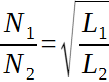
the secondary winding will have an inductance defined by:
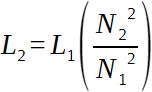
or 6.31μH. Enter 6.31uH for the inductance and click OK.
Placing a Linear Core Model
Step 8: With the winding inductors placed, the magnetic core must be defined. Select Place > Component from the menu
Step 9: The Component Explorer tab opens. Here you can place components with pre-defined SPICE models as well as components from SamacSys, Ultra Librarian, and other sources. Select the PSpice category.
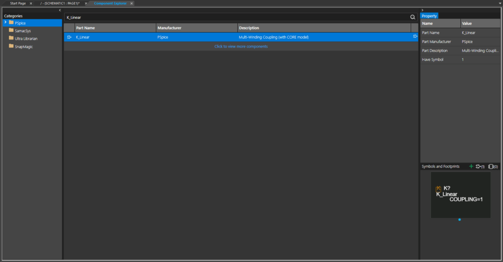
Step 10: Enter K_Linear into the Search field and press Enter. The list is filtered to show the K_Linear core model.
Note: Other core models available in the Component Explorer include:
- Kbreak: A breakout core model to represent nonlinear cores.
- Kcouple[2-5]: Asymmetric coupling matrices for advanced modeling. The number defines the matrix size.
Step 11: Double-click the model listing to attach it to your cursor.
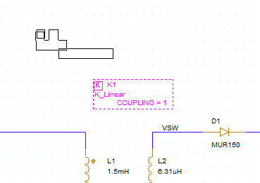
Step 12: Click to place the core model in the schematic canvas. Right-click and select End Mode.
Defining Core Parameters
Step 13: The magnetic core windings and coupling must be defined before the flyback transformer works as intended. Select the core and double-click it to open the Property Editor tab.
Step 14: The Property Editor tab opens for the core. Here you can define all component properties including windings and coupling. Select the cell for L1 and enter L1 into the empty field. Select the cell for L2 and enter L2 into the empty field.
Note: This will assign inductors L1 and L2 to the first and second windings on the core, respectively. Up to six windings can be assigned to one core.
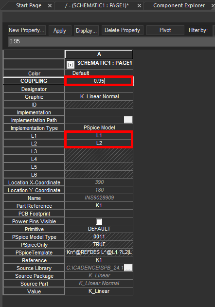
Step 15: Enter 0.95 for the Coupling.
Step 16: Click Apply and close the Property Editor tab.
Defining a Simulation
Step 17: To confirm that the flyback transformer works as intended, a simulation must be created. Select PSpice > New Simulation Profile from the menu.
Step 18: The New Simulation window opens. Enter FLYBACK_TRANS for the simulation name and click Create.
Note: If the PSpice Simulation Manager Product Choices window opens, select the appropriate license and click OK.
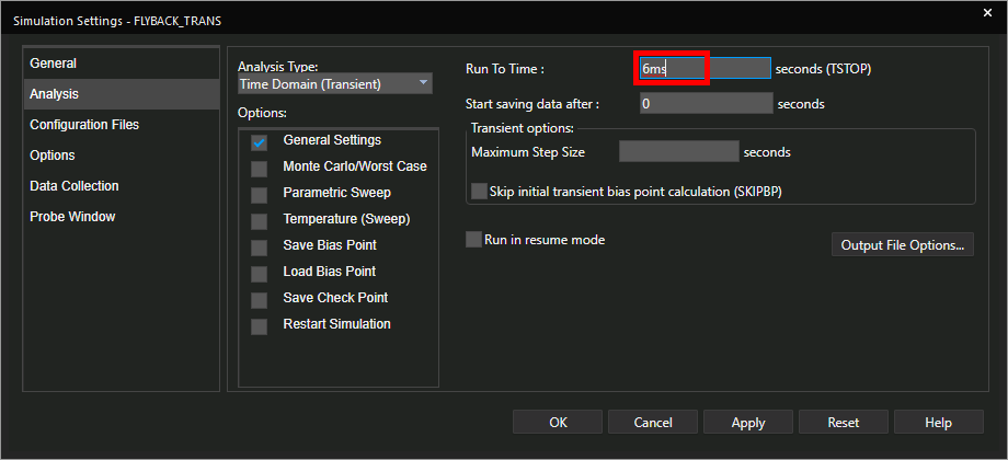
Step 19: The Simulation Settings window opens. Here you can define the type of simulation to run and all simulation options. Enter 6ms for the Run To Time to run the simulation to 6 milliseconds.
Step 20: Leave the other settings as the defaults and click OK.
Step 21: Select the Voltage/Level Marker button from the toolbar.
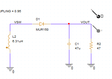
Step 22: Click to place a probe on the VOUT net.
Step 23: Select the Current Marker button from the toolbar.
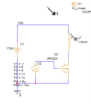
Step 24: Click to place a current probe at the input of the primary inductor. Right-click and select End Mode.
Running the Simulation
Step 25: Select PSpice > Run from the menu to start the simulation.
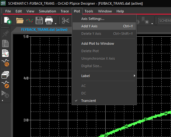
Step 26: The PSpice A/D window opens to show the output voltage and input current on the same plot. To make the plot easier to read, select Plot > Add Y Axis from the menu.
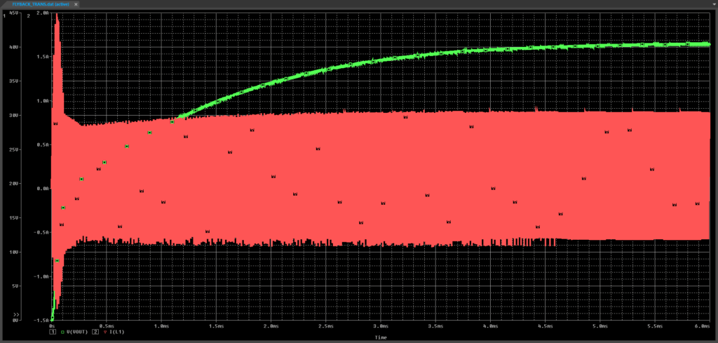
Step 27: Select the I(L1) marker from the legend and press CTRL-X on the keyboard to cut the trace. Press CTRL-V to place the trace in the new Y axis scale. The output voltage and current are now shown within their own ranges.
Wrap Up & Next Steps
Quickly model magnetic parts for accurate simulation of components such as transformers in PSpice Designer. Test out this feature and more with a free trial of OrCAD X. Want to learn more about PSpice? View additional how-tos, walk-throughs, and courses at EMA Academy.

