In some applications, such as medical and automotive, not only do boards have a circular outline but placement and routing must be completed in a circular fashion. Achieving a PCB layout and routing for these types of boards using a cartesian grid is time consuming and cumbersome. Quickly place components in a grid with polar coordinates with the Polar Grid feature in the Allegro Productivity Toolbox. Efficiently complete PCB layout for circular boards with functionality including:
- Polar Grid Definition
- Polar Placement
- Polar Routing
- Polar Shapes Including Voids
This how-to will provide step-by-step instructions for placing components using a Polar Grid with OrCAD PCB Designer Professional and Allegro Productivity Toolbox.
How-To Video
Configuring the Polar Grid
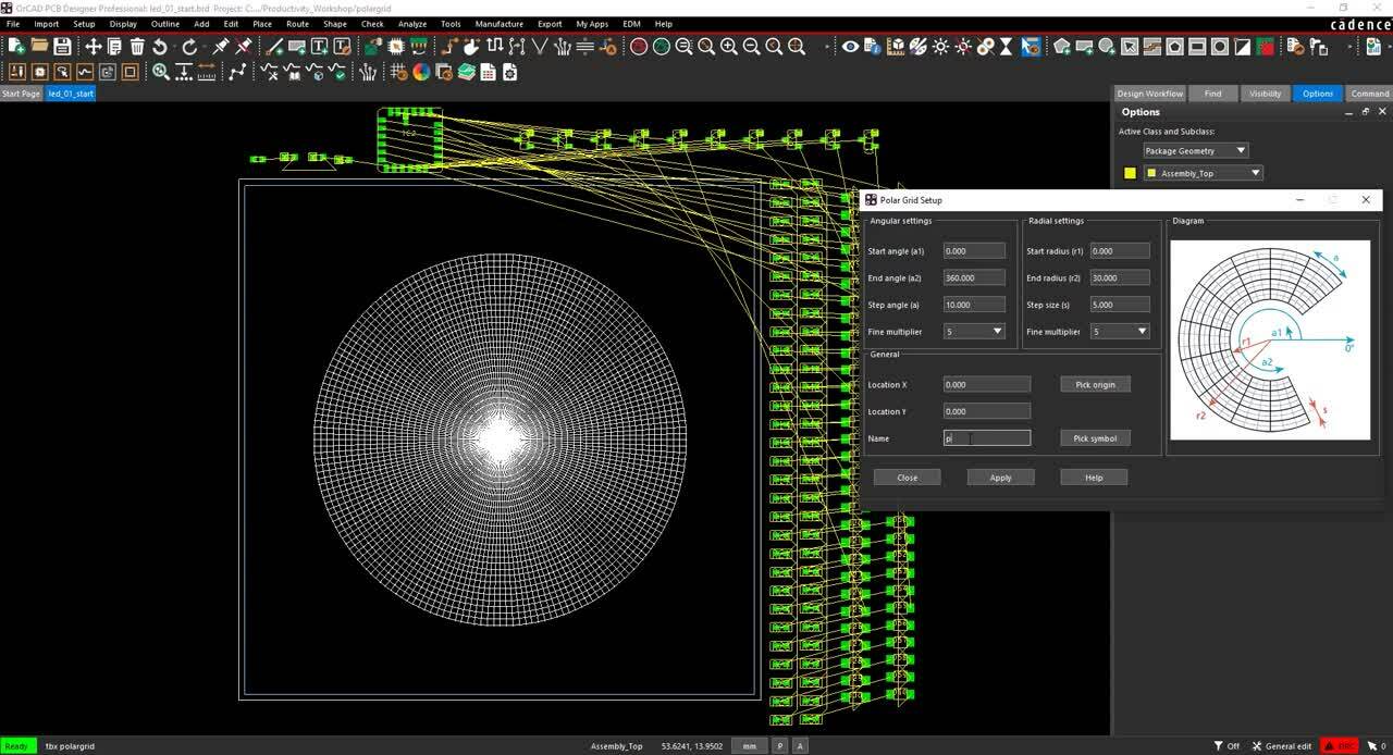
Step 1: Open the desired design in OrCAD PCB Designer Professional with the Allegro Productivity Toolbox option selected.
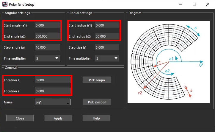
Step 2: Select Setup > Polar Grid > Setup from the menu.
Step 3: Under Angular Settings, set the Start Angle to 0 and the End Angle to 360.
Step 4: Under Radial Settings, set the Start Radius to 0 and the End Radius to 30.
Step 5: Under General, set the Location X to 0 and the Location Y to 0.
Note: The location specifies the origin on the polar grid. Pick Origin can be used to select the origin on the PCB canvas.
Step 6: Set the name to pg1.
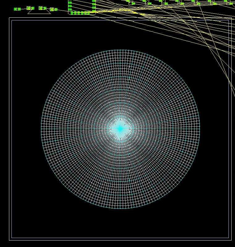
Step 7: Click Apply and Close. The Polar Grid is generated.
Next, we will show to place components on the grid you have just generated.
Placing Components on a Polar Grid
Step 8: Select Setup > Polar Grid > Place from the menu to activate the component placement mode.
Note: The following placement modes are available for polar grids:
- Place: The component will be placed at the destination location without further action.
- Place and Spin: The component will be placed at the destination location first then the user is asked to specify rotation.
- Spin Only: The selected component will be rotated at the current position.
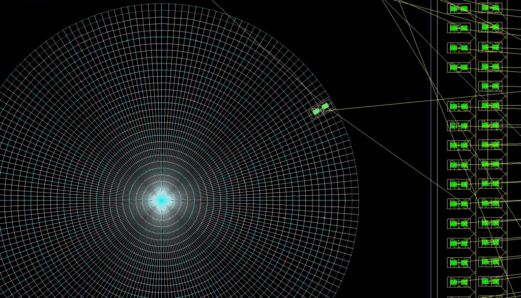
Step 9: Click a component to select it and click again to place it in the polar grid.
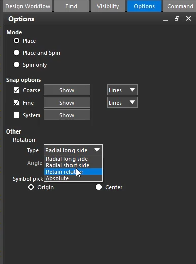
Step 10: In the Options panel, select Radial Short Side from the Type drop-down menu under Rotation.
Note: This option applies to the component alignment with respect to the current position in the polar grid. The following options are available:
- Radial Long Side Rotation: Rotation will be adjusted so that the angle of the longest side lies on the radial axis.
- Radial Short Side: Rotation will be adjusted so that the angle of the shortest side lies on the radial axis.
- Absolute: Rotation is fixed and can be specified in the Angle field.
- Retain Relative: Current rotation will be retained. This is useful if the initial relative rotation is not allowed to be changed when moving the component from one grid location to another.
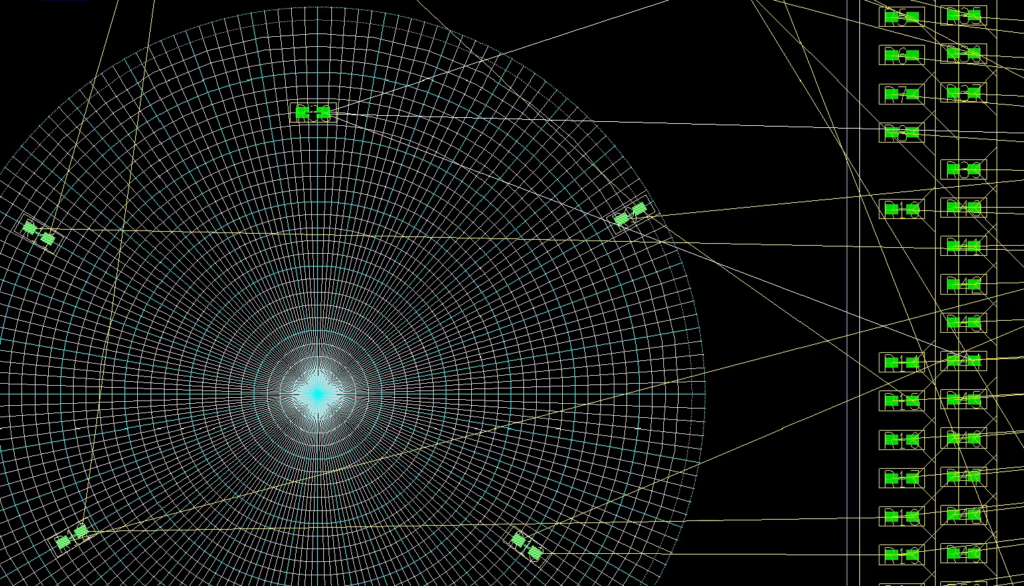
Step 11: Click additional components and place them on the grid. The angle at which the components are placed has been changed.
Next, we will show you how to view the grid with components placed on your board.
Viewing the Board
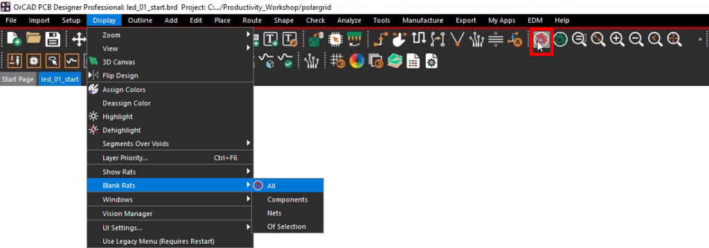
Step 12: Select Display > Blank Rats > All from the menu or the Blank Rats button from the toolbar.
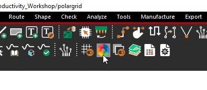
Step 13: Select the Color192 button from the toolbar to activate the Color Dialog.
Step 14: Select the Manufacturing panel from the list on the left side of the Color Dialog window.
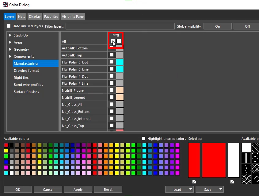
Step 15: Uncheck the checkbox labeled Mfg to disable all Manufacturing layers.
Note: Click the checkbox once to turn all layers on, then click it again to disable all layers.
Step 16: Click OK to save the settings and close the window.
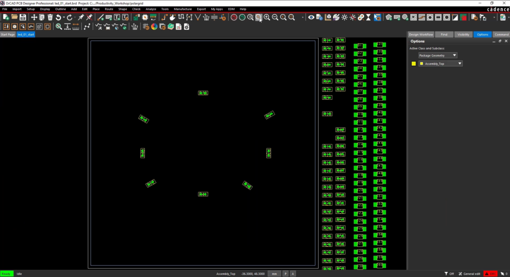
Step 17: Select the Zoom Fit button from the toolbar to see the entire board.
You have just gone through the steps to create and place components on a polar grid.
Wrap Up & Next Steps
Quickly and efficiently place components on a Polar Grid with Allegro Productivity Toolbox and OrCAD PCB Designer. Learn more about the time-saving features included in Allegro Productivity Toolbox in this free webinar.

