When starting a schematic design, it’s important to note how fine the component placement grid is to ensure proper connectivity. Additionally, not snapping to a grid will not only make the design less readable but increase the possibility of missed connections between components. Easily leverage placement grids in OrCAD X Capture to improve readability and ensure complete connections.
This quick how-to will provide step-by-step instructions on how to use placement grids in OrCAD X Capture.
How-To Video
 Open in New Window
Placement Grids in OrCAD: Spacing
Step 1: Open OrCAD X Capture.
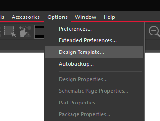
Step 2: To configure default grid settings, select Options > Design Template from the menu.
Step 3: The Design Template window opens. Here you can configure all default settings for a new design, including font, title block, hierarchy, and more. Select the Page Size tab.
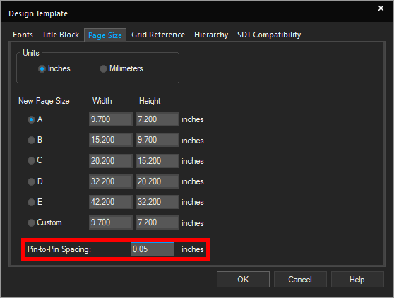
Step 4: In the Page Size tab, you can define design units and the size of the page. Enter 0.05 inches for Pin-to-Pin Spacing. This will create a finer grid for new designs.
Step 5: Click OK to save the settings and close the window.
Creating a New Design
Step 6: To create a new design in OrCAD X Capture, select File > New > Project from the menu.
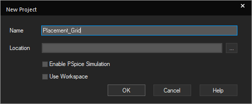
Step 7: The New Project window opens. Enter a name for the project. Uncheck Enable PSpice Simulation and Use Workspace to save the file locally and not use PSpice simulation.
Step 8: Select the ellipsis. Browse for a location to save the file and click Select Folder.
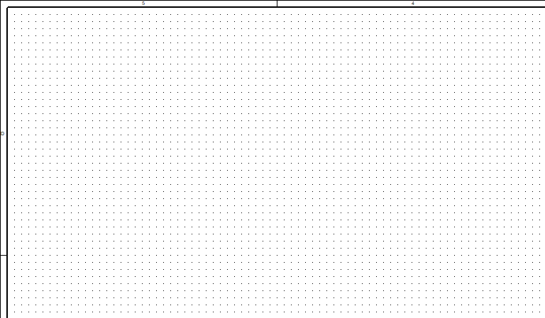
Step 9: Click OK to create the project. A blank schematic page opens.
Placement Grids in OrCAD: Visibility
Step 10: To make the grid more visible, select Options > Preferences from the menu.
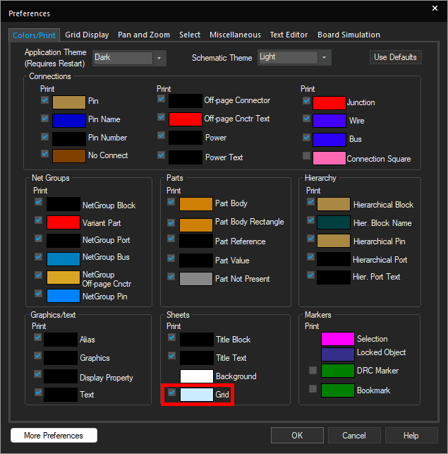
Step 11: Select the Colors/Print tab if it is not already open. The application theme settings are shown. Here you can configure the colors used for all elements in the schematic.
Step 12: Select the color space for Grid.
Step 13: Choose a dark color from the Grid Color dialog and click OK.
Note: If running the Capture canvas in a dark theme, select a light color.
Step 14: Click OK to save the settings and close the window. The grid markers now have a stronger contrast.
Placement Grids in OrCAD: Confirm Spacing Settings
Step 15: To confirm the set spacing settings, select Options > Schematic Page Properties from the menu.
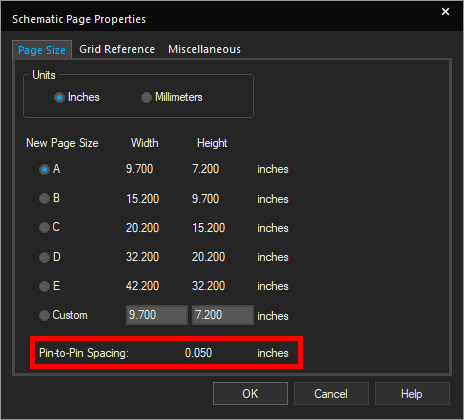
Step 16: The Schematic Page Properties window opens to the Page Size tab. View the Pin-to-Pin spacing at the bottom. The spacing is shown to be 0.05”, as configured when the page was created.
Step 17: Close the Schematic Page Properties window.
Placement Grids in OrCAD: Grid Snapping
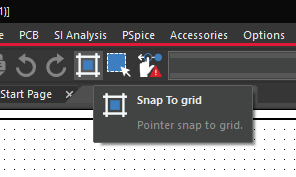
Step 18: Grid snapping can be toggled off to draw shapes or diagrams in a schematic page with even finer dimensions. To do this, select Snap to Grid from the toolbar.
Note: The icon for this button changes to a single grid space.
Step 19: To test the non-grid placement, select Place > Polyline from the menu.

Step 20: Click to start drawing a polyline in the canvas. While the points can get close to the grid markers, they do not automatically snap.
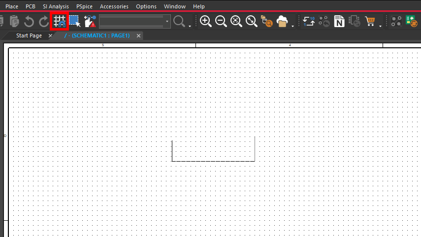
Step 21: Select Grid Snapping again. The icon turns into a grid with a magnet, indicating that snapping is active. The polyline now snaps to the grid markers. Press Escape to detach the polyline from your cursor and draw whatever was placed.
Note: Always use grid snapping when placing components or routing wires to ensure they connect properly.
Wrap Up & Next Steps
Use placement grids in OrCAD X Capture to ensure a neat and connected schematic. Test out this feature and more with a free trial of OrCAD. Want to learn more about Capture? Get access to free how-tos, courses, and walk-throughs at EMA Academy.

