
PCB Design
How to Create a Hierarchical Block Diagram in OrCAD X Capture
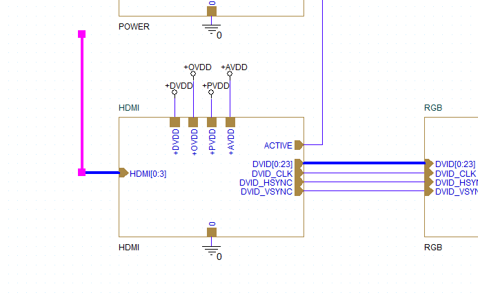
Learn how to create a hierarchical block diagram in OrCAD X Capture to expedite the design process and ensure your design intent remains clear throughout.

Learn how to create a hierarchical block diagram in OrCAD X Capture to expedite the design process and ensure your design intent remains clear throughout.
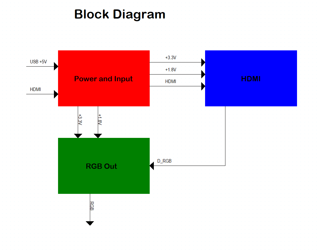
Learn how to create a block diagram in OrCAD X Capture to communicate a high-level overview of the PCB design and ensure your design intent remains clear throughout.
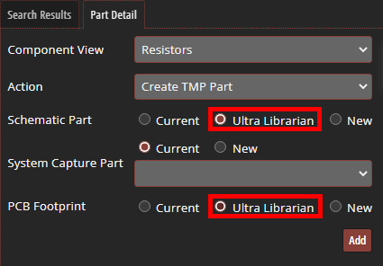
Learn how to create design with temporary parts to streamline the development process when new part introduction is required with CIP.
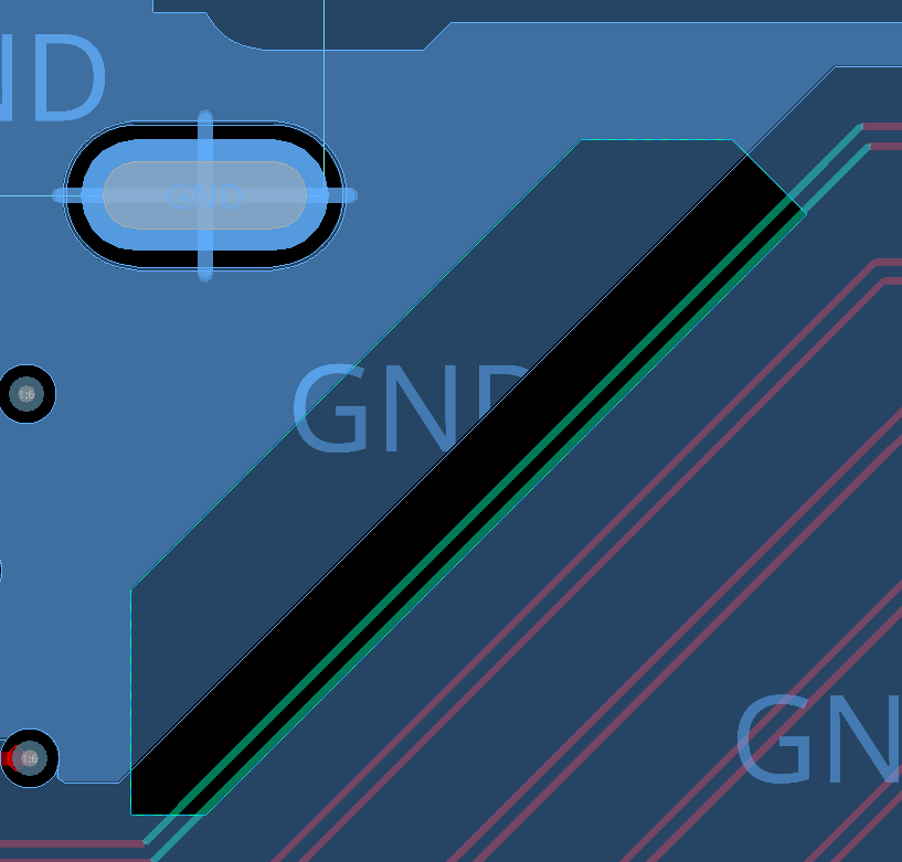
Learn how to detect trace segments over voids in OrCAD X PCB Designer to optimize signal integrity.

Learn how to configure tables in CIP to improve parameter visibility for components in your part database and streamline component management.
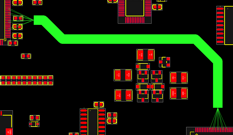
Learn how to configure bundles and flows in Allegro X to plan routing on a PCB and expedite the layout process.
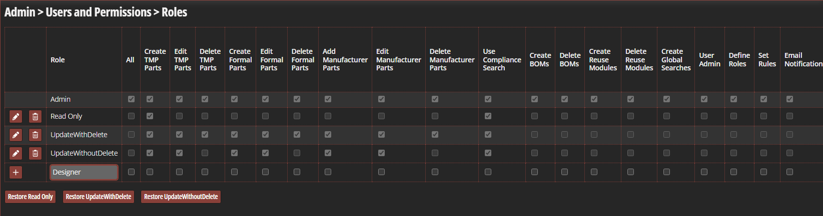
Learn how to define user roles and permissions in CIP to ensure data integrity for your component database.
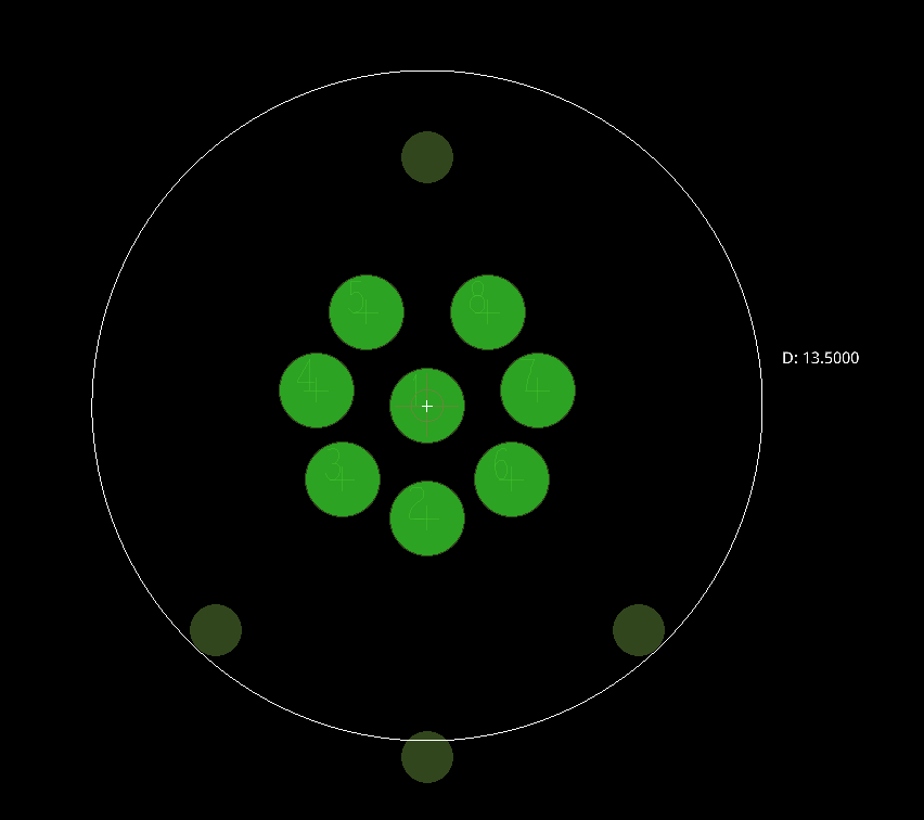
Learn how to create a PCB footprint for a circular connector in OrCAD X.
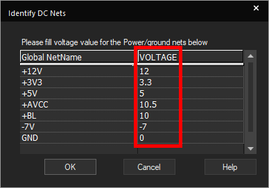
Learn how to assign voltage values to DC nets directly in the schematic canvas to ensure clarity of design intent.
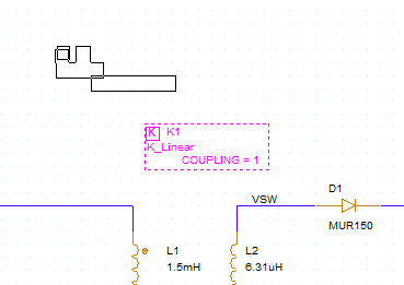
Learn how to model magnetic parts in PSpice for components such as transformers to produce accurate simulations.
