As vehicles evolve into sophisticated mobile computers (much like how phones transformed into smart devices) the demand for faster, more reliable data transfer continues to grow. Modern automotive systems rely on a wide range of sensors and cameras for applications such as overhead view image stitching, driver assistance, and autonomous driving. To support these data-intensive functions, designers have turned to proven, industry-standard interfaces. The Mobile Industry Processor Interface (MIPI), originally developed for the mobile industry, has emerged as an optimal solution for automotive and sensor-based applications. Its advantages in bandwidth, efficiency, and electromagnetic performance far exceed those of traditional automotive interfaces such as CAN and I²C. In this article, we’ll explore why MIPI is ideally suited for these advanced automotive systems and share key tips for qualifying your MIPI interfaces for first-pass success.
Meeting Automotive Design Requirements with MIPI Interfaces
MIPI is predominantly used in automotive ADAS design (Autonomous Driving) to adhere to specific design requirements as seen below.
| Design Requirement | MIPI | CAN | I2C |
| Battery Powered | Low Energy Transport Solution
|
Moderate Power Usage | Low Power |
| Surround View Cameras | High Bandwidth | Low Bandwidth | Very Low Bandwidth |
| Minimal Interference | EMI Mitigation
|
Good Noise Immunity | Moderate Noise Immunity |
| Dynamic Driving Conditions | Vibration Resistance | Good Mechanical Robustness | Limited Robustness in Harsh Environments |
| Functional Safety | ISO26262 Adherence | Used in Safety-Critical Systems | Not Typically Used in Safety-Critical Systems |
| Reliability | Proven Implementation
|
Low Cost | Low Cost |
Battery Powered Operation
Automotive design relies on battery powered operation, which is limited. MIPI devices have low energy transport and low power idle mode which is critical to conserve power. For autonomous driving applications, minimal battery power should be used. MIPI devices are ideal for this configuration as they can operate solely in low-power mode.
Surround View Cameras
Autonomous driving incorporates a plethora of surround view cameras which requires a large volume of data to be transferred from the cameras to the processor. MIPI devices have a high bandwidth, with the ability to transfer 1.25Gb/sec per differential pair. With 4 differential pairs per interface, approximately 5Gb/sec data transfer can be achieved.
Minimal Interference
With automotive applications, there is always going to be high interference from 5G, LTE, and Wi-fi signals. To ensure proper operation, MIPI offers a robust protocol for EMI mitigation and noise reduction.
Dynamic Driving Conditions
In automobiles, there are a lot of vibrations and dynamic driving conditions that must be accounted for to create a robust, functional system. MIPI deploys a vibration-controlled environment.
Functional Safety
The automotive industry must adhere to strict safety standards as defined in ISO26262. These standards are monitored and governed within MIPI interface protocol, enabling designers to easily adhere to the requirements outlined in these industry standards.
Reliability
MIPI functionality and reliability has been implemented successfully in billions of mobile devices. This proven track record coupled with ability to easily adapt to automotive applications makes MIPI the ideal low-cost solution for autonomous driving data transfer.
While the benefits of MIPI in automotive design are abundant, the implementation introduces additional design considerations that must be addressed to create a functional PCB which adheres to industry-standard requirements.
Understanding MIPI PHY Specifications for Reliable Data Communication
To achieve the high-performance and reliable communication required for automotive applications and other fields which incorporate MIPI such as aerospace, military, and more, the MIPI alliance has developed interface specifications. For PCB design and hardware, physical layer (PHY) specifications should be referenced which outline specific protocols, interface standards and compliance requirements based on the type of device.
| PHY Specification | Description | Features |
| A-PHY | SerDes specification for advanced automotive technology and other applications. | ✅ 32 Gbps Data Rate
|
| C-PHY | Encoded camera and display data transfer. | ✅ Low EMI
|
| D-PHY | Differential signaling protocol specifications for 4 meter or less interconnection. | ✅ Low EMI
|
| M-PHY | Multimedia and Inter- Processor Communication (IPC) communication interface specifications. |
|
When building MIPI compliant devices, circuit boards, and systems, analyzing adherence to device standards must be incorporated into your PCB design process. Regardless of which MIPI device is being utilized in the design, steps can be taken to achieve MIPI compliance the first time:
Step 1: Know what MIPI PHY interface parameters to check
Step 2: Simulate board and MIPI interface functionality
Step 3: Analyze results for compliance to MIPI PHY standards
Step 4: Follow MIPI design guidelines to fix any problems
Step 5: Produce the design and perform MIPI PHY conformance testing
By following these steps and incorporating MIPI compliance analysis into the PCB design process, performance issues can be identified when change is easiest. Designers can easily adjust the PCB layout to improve performance and ensure designs containing MIPI devices are compliant before manufacturing and conformance testing.
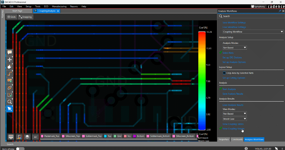
Analyzing and Optimizing MIPI Performance with Sigrity X
Sigrity X creates a unified environment for PCB design and analysis enabling engineers to evaluate and improve MIPI performance throughout the layout process. With Sigrity X, designers can analyze critical MIPI performance parameters including:
- Impedance
- Crosstalk
- Insertion loss
- Return Loss
- TDR plots
Learn more about how Sigrity X can help you achieve compliance with MIPI standards and see how customers have implemented a unified environment for their MIPI design and analysis here.