Counterbore and countersink holes used on the secondary side of the PCB can enhance functionality and ensure proper fit of components through:
- Improving Component Clearance
- Ensuring Mechanical Stability
- Guaranteeing Connector or Port Alignment
- Improving Aesthetics
- Reducing Stress Concentration
New in OrCAD X 23.1 is the ability to quickly add counterbores and countersinks to the secondary side of a padstack in the padstack editor.
This quick how-to will provide step-by-step instructions on how to create counterbores and countersinks in OrCAD X and Allegro X.
How-To Video

Viewing Existing Countersinks
Step 1: Open a design with countersinks in Allegro X Venture.
Note: This feature is available in all versions of OrCAD X and Allegro X.
Step 2: Select View > 3DX Canvas from the menu or the 3DX button from the toolbar.
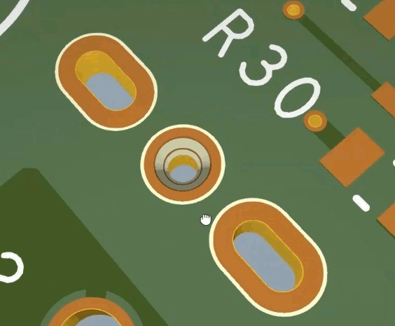
Step 3: Zoom into the padstack with a countersink on top. A countersink is distinguished by a chamfer at the top of the hole.
Note: Scroll the mouse wheel to zoom in or out. Hold the middle mouse button to pan the view. Hold Shift while holding the middle mouse button to rotate the view.
Step 4: Close the 3DX canvas.
Adding a Countersink to the Bottom
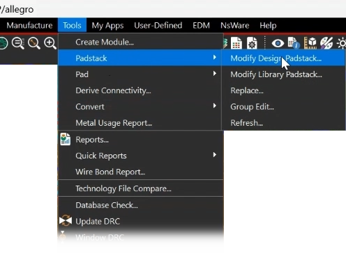
Step 5: Select Tools > Padstack > Modify Design Padstack from the menu.
Step 6: In the PCB canvas, select the desired padstack to change or select from the list of padstacks provided in the options tab.
Step 7: Right-click the padstack and select Edit. The Padstack Editor opens.
Step 8: Select the Secondary Drill tab.
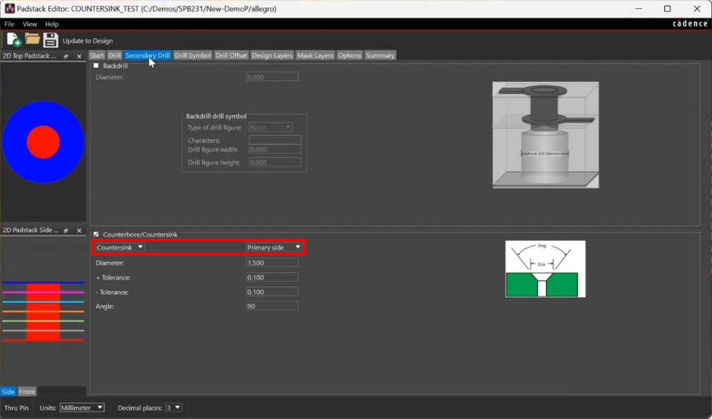
Note: A countersink has already been designed for the primary (top) side.
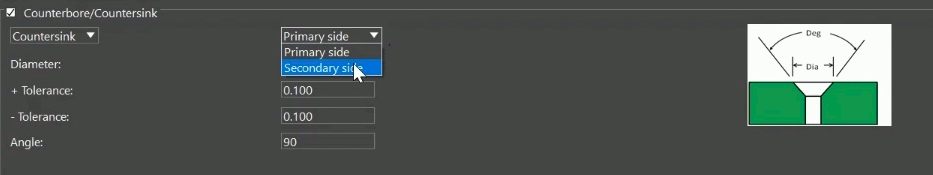
Step 9: Select Secondary Side from the right-side dropdown.
Note: Select Counterbore from the left-side dropdown to change the secondary drill to a counterbore.
Step 10: Change the diameter to 1.8.
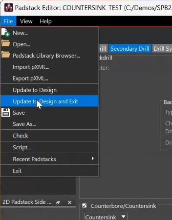
Step 11: Select File > Update to Design and Exit from the Padstack Editor menu.
Note: To update the padstack instance without exiting, select Update to Design.
Step 12: Right-click and select Done in the Allegro canvas.
Confirming the Change
Step 13: Select View > 3DX Canvas from the menu or the 3DX button from the toolbar.

Step 14: Zoom into the top of the changed padstack. The top no longer has a countersink.

Step 15: Rotate the view to the bottom of the board. The countersink has been moved to the bottom of the pad.
Wrap Up & Next Steps
Quickly create counterbores and countersinks on the primary or secondary sides of the PCB in OrCAD X and Allegro X. Upgrade to 23.1 to test out this and other new features in OrCAD and Allegro.

