Every PCB manufacturer has a different set of requirements for manufacturability that a PCB must comply with to prevent delays and errors. Manually defining Design for Manufacturing (DFM) rules can be time-consuming and prone to errors, requiring research into manufacturers capabilities, associated costs, and entry of critical values into your CAD software. The DesignTrue DFM Wizard can be used to quickly and easily assign DFM rules to a design in OrCAD X.
This quick how-to will provide step-by-step instructions on how to automatically assign manufacturing rules with DesignTrue DFM in OrCAD X.
To follow along, download the provided files above the table of contents.
How-To Video
 Open in New Window
Activating the DesignTrue DFM Wizard
Step 1: Open the provided design in OrCAD X.
Step 2: Select Constraints at the bottom of the Properties panel to open the Constraints panel.
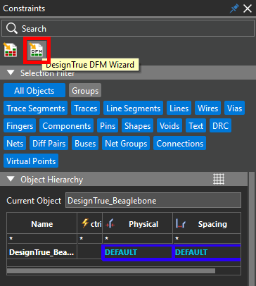
Step 3: The Properties panel changes to the Constraints panel, showing the default constraint sets assigned for this design. Select the DesignTrue DFM Wizard button at the top of the Constraints panel.
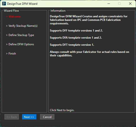
Step 4: The DesignTrue DFM Wizard opens to the Welcome panel, showing the Wizard’s capabilities. Click Next to start the wizard.
Automatically Assign Manufacturing Rules with the DesignTrue DFM Wizard
Step 5: The Wizard Flow subpanel on the side shows the current step. The first panel of the wizard verifies the number of stackups and their names. Click Next.
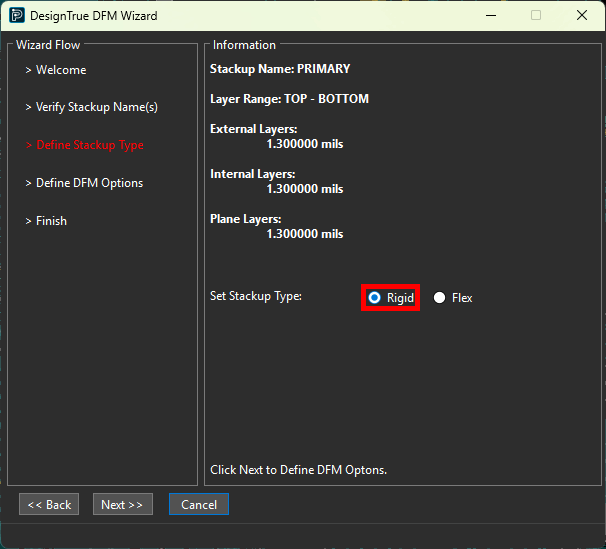
Step 6: The next panel shows the layer range and thicknesses for each stackup. Select Rigid under Set Stackup Type. Click Next.
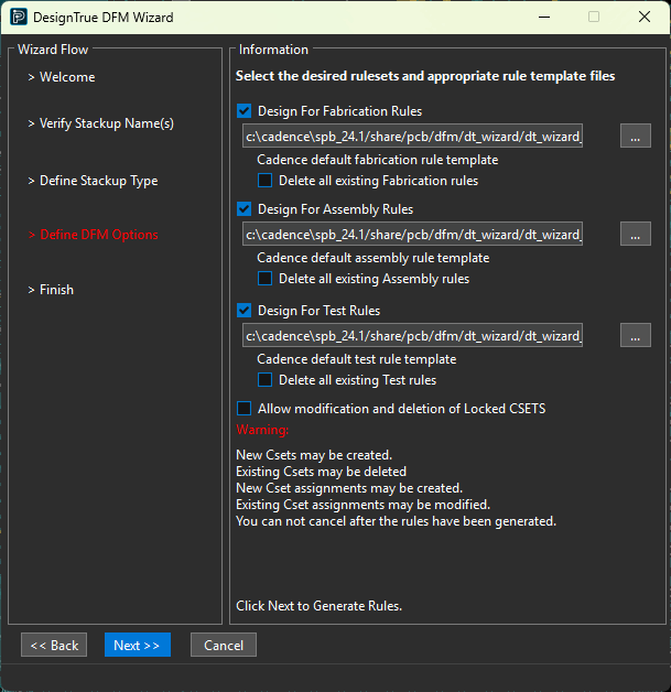
Step 7: The next panel shows the DFM option templates to use. By default, Cadence has included template files, populated based on IPC standards and common PCB fabrication requirements, which are pre-loaded into the DFM Wizard. For this example, leave these default settings and click Next to generate the rules.
Note: Additional pre-configured templates from industry-leading manufacturers are available from the DFM Partner Portal. Users can also create custom manufacturing rules in a CSV file following a templated format. The following steps can be used to create a custom CSV file:
Step 1: To view the default DesignTrue wizard templates, open File Explorer.
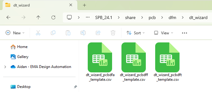
Step 2: Browse to the default location for DesignTrue wizard templates: C:\Cadence\SPB_[version]\share\pcb\dfm\dt_wizard.
Step 3: A template file for each branch of DFM is shown. Open dt_wizard_pcbdff_template.csv in a spreadsheet editor such as Microsoft Excel or LibreOffice Calc to view the Design for Fabrication rules. If prompted for the type of separator, select Comma.
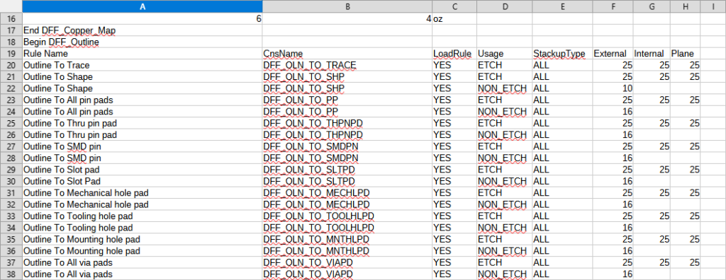
Step 4: View the rule table. All default Cadence Design for Fabrication rules to be assigned are shown in mils.
Step 5: Copy the file and modify the rules based on your specific PCB manufacturing requirements.
Step 6: Complete this process for the fabrication, assembly, and testing requirements as needed.
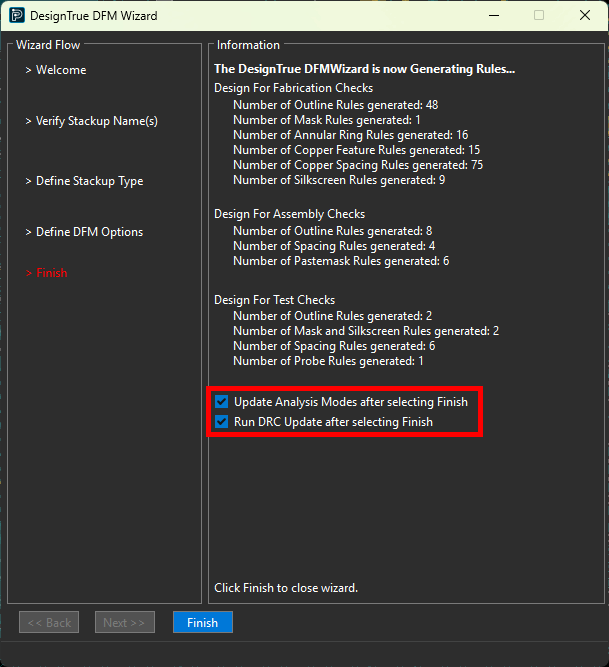
Step 8: The last panel shows the number of rules generated for each DFM component. Check the options to Update Analysis Modes. This will automatically activate any rule checking for the DFF, DFA, or DFT rules being configured.
Step 9: Check the option for Run DRC Update. This will automatically perform a design rule check on the PCB incorporating the newly defined DFM rules.
Step 10: Select Finish to close the wizard.
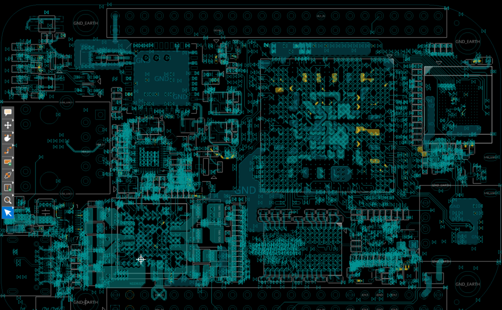
Step 11: View the PCB canvas. New errors are shown from the newly-generated constraints.
Note: Learn how to identify and correct design rule errors in OrCAD X here.
View DFM Rules for your PCB Design
Step 12: Rules added by the DFM Wizard can be viewed in the Constraint Manager. Select Tools > Constraint Manager from the menu.
Step 13: The Constraint Manager opens. Select the Manufacturing domain from the Worksheet Selector.
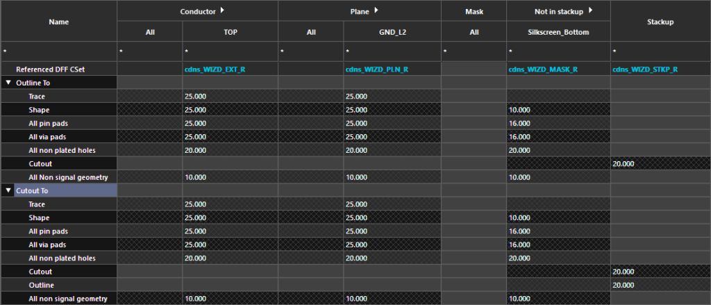
Step 14: Expand the Design for Fabrication > DFF Constraint Set workbook and select the Outline worksheet.

Step 15: Expand the Outline To and Cutout To rows in the constraint table to view the constraint sets added by the DFM Wizard. The rules defined in the template have been added.
Step 16: Expand the Design for Fabrication > Design workbook and select the Outline worksheet.
Step 17: Expand the Outline To and Cutout To rows in the constraint table to view the assigned constraint sets. Double-click to expand Conductor to view the assignments for each layer.
Step 18: Select the other worksheets to view the additional constraint set assignments for the fabrication, assembly, and testing requirements.
Wrap Up & Next Steps
Automatically assign manufacturing rules with the DesignTrue DFM Wizard in OrCAD X to quickly setup the required fabrication, assembly, and testing constraints for your PCB designs and ensure first-pass success. Test out this feature and more with a free trial of OrCAD X. For more how-tos and step-by-step walk-throughs, visit EMA Academy.

