When designing modules such as power supply circuits, amplifier circuits, and digital processors, it’s easy to recognize the importance of keeping noise out of the circuit output. However, it is just as important (and often overlooked) to prevent the noise from feeding back into the input. Typically, this noise is mitigated with ferrite beads. PSpice Designer allows you to create a ferrite bead SPICE model to accurately simulate circuit functionality and noise reduction.
This quick how-to will provide step-by-step instructions on how to create a ferrite bead SPICE model in PSpice Designer.
To follow along, download the provided files above the table of contents.
How-To Video
 Open in New Window
Running a Simulation Without a Ferrite Bead
Step 1: Open the provided design in PSpice Designer.
Step 2: Select PSpice > New Simulation Profile from the menu.
Step 3: In the New Simulation window, enter SMPS_Trans for the name and click Create.
Note: If the Simulation Manager Product Choices window opens, select the appropriate license and click OK.
Step 4: The Simulation Settings window opens. Here you can define the type of analysis, analysis settings, and configuration files. Enter 10m for the Run To Time and 50n for the Maximum Step Size.
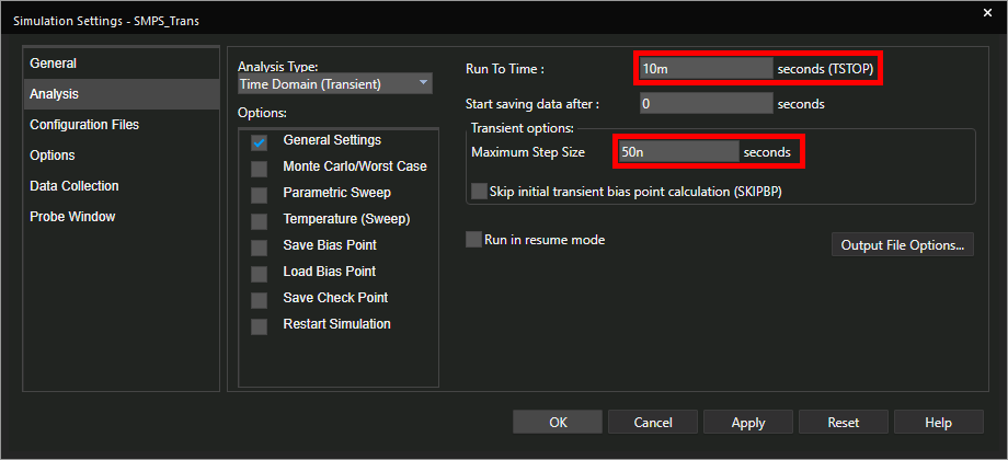
Step 5: Leave the other settings as the defaults and click OK.
Step 6: Select the Voltage/Level Marker button from the toolbar to place a voltage probe.
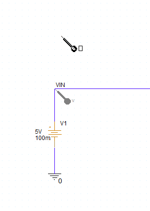
Step 7: Click to place a probe on the VIN net. Right-click and select End Mode.
Step 8: Select PSpice > Run from the menu to run the simulation.
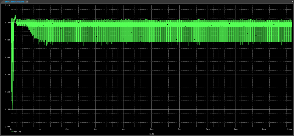
Step 9: The PSpice A/D window opens to show the simulation results. The input voltage is littered with voltage spikes, which could easily introduce noise or damage other components. This can be corrected by adding a ferrite bead.
Close the PSpice A/D window.
Interpret a Ferrite Core Datasheet
Note: Ferrite beads can exhibit non-linear impedance properties. For accurate analysis results, we will create a ferrite bead SPICE model based on datasheet parameters.
Step 10: Open the provided datasheet 7427502.pdf in your preferred PDF viewer.
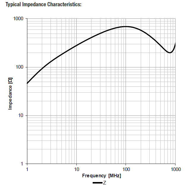
Step 11: Scroll to the second page and view the impedance characteristic curve. The impedance increases with frequency, drops briefly, then continues up. This curve will be used as a reference to create a ferrite bead in PSpice.
Minimize the PDF viewer.
Create a Ferrite Bead SPICE Model
Step 12: Open the provided ferrite_bead.lib in a text editor of your choice, such as Notepad.
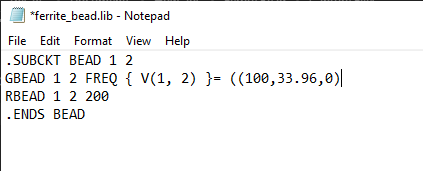
Step 13: The file opens to show some preliminary SPICE code. The code defines a subcircuit titled BEAD with two nodes. The gain/attenuation between the two nodes is defined as frequency table with the FREQ keyword and the RBEAD keyword defines a resistance across the nodes for a Real shunt impedance.
Add the expression ((100,33.96,0) to the right side of the equals sign.
Note: This defines the gain magnitude or relative admittance to be 33.96dB and the gain phase to be 0° at 100Hz. Admittance is defined instead of impedance because the current through the model is defined as a constant times the voltage, not the other way around.
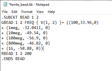
Step 14: Add the following lines below the edited line:
+ (1meg, -32.0411, 0)
+ (10meg, -49.54, 0)
+ (100meg, -56.9, 0)
+ (800meg, -46.02, 0)
+ (1G, -50.88, 0))
Note: Each magnitude is taken by reciprocating the impedance at that frequency, according to the impedance plot in the datasheet, and calculating the value in decibels. In other words:
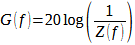
Phase shift can be incorporated as well, if it is known. If the datasheet lists phase shift, add the phase at each frequency in degrees as the third argument in each line.
Step 15: Save and close the text file.
Create a Ferrite Bead SPICE Model: Part Creation
Step 16: Back in Capture, select File > New > Library from the menu.
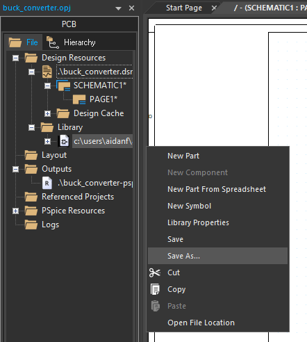
Step 17: The library is added to the Project Manager in the Library folder. Right-click the library and select Save As to name it.
Step 18: Browse to the working directory. Name the library Ferrite_Bead.olb and click Save.
Step 19: Right-click the library and select New Part.
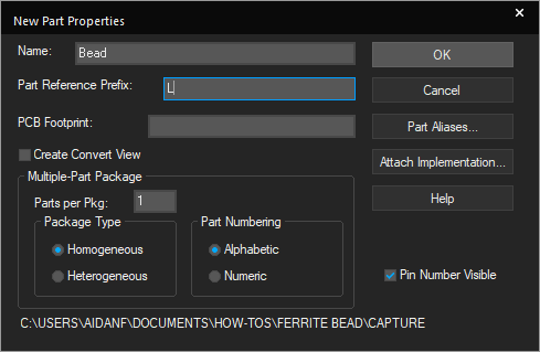
Step 20: The New Part Properties window opens. Enter Bead for the name and L for the Part Reference Prefix. Leave the other settings as the defaults and click OK.
Step 21: In the Part Editor tab, adjust the outline to be five grid spaces wide by two spaces high.
Step 22: Select Place > Rectangle from the menu.
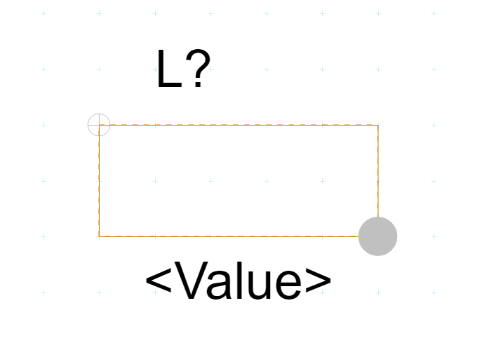
Step 23: Click to draw a rectangle to cover the entire outline. Click again to finish.
Step 24: Select Place > Pin from the menu.
Step 25: In the Place Pin window, enter 1 for the pin name and number. Set the shape to Short.Click OK to place the pins.
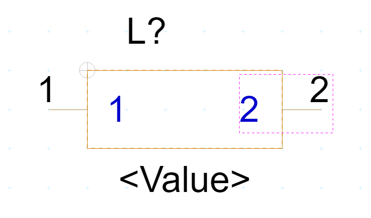
Step 26: Click to place a pin on each end of the part. Right-click and select End Mode when finished. The pin number is incremented automatically.
Step 27: Select Associate PSpice Model from the Properties panel.
Step 28: A prompt appears that the symbol has been modified and must be saved. Click Yes.
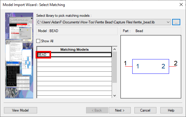
Step 29: The Model Import wizard opens. Select the ellipsis and browse to the provided ferrite_bead.lib file. Choose the file and click Open. The matching model is selected automatically. Click Next.
Step 30: Pin mapping must be defined next. In the Symbol Pin column of the table, select 1 and 2 from the dropdown for each row in the Model Terminal column such that the model terminal and symbol pin match.
Step 31: Click Finish. The model is associated. Close the Part Editor tab.
Place the Ferrite Bead
Step 32: Select Place > Part from the menu.
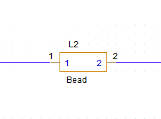
Step 33: The Place Part panel opens. Select FERRITE_BEAD from the library list and Bead from the Part List.
Note: The PSpice symbol at the bottom of the panel indicates that a PSpice model is attached.
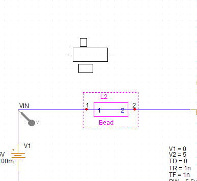
Step 34: Click Place Part and click to place the bead between V1 and M1. Right-click and select End Mode.
Step 35: The wire segment between the bead endpoints will remain intact and must be removed for the simulation to run. Select the wire segment between the bead endpoints and press Delete on the keyboard. The bead has split VIN into two nets.
Linking the Simulation Model
Step 36: Before the simulation can be run again to verify the fix, the SPICE code for the bead must be added to the configuration file for the simulation. Select PSpice > Edit Simulation Profile from the menu.
Step 37: In the Simulation Settings window, select Configuration Files from the table on the left.
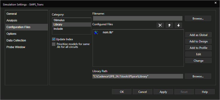
Step 38: Select Library under Category. A list of configured library files is shown.
Step 39: Select Browse. Browse to and select the provided ferrite_bead.lib file. Click Open.
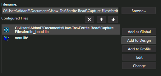
Step 40: Select Add to Design to add the code to the Configured Files list. The code has been added to the simulation for the current design. Click OK.
Note: Select Add as Global to add the model code to all future simulations.
Running the Updated Simulation
Step 41: With the ferrite bead placed, select PSpice > Run from the menu to rerun the simulation.
Step 42: The PSpice A/D window opens. At first glance, the noise looks like it has worsened; however, it only appears so because the plot view is zoomed in. To fix this, select Plot > Axis Settings from the menu.
Step 43: Select the Y Axis tab to adjust Y axis settings.
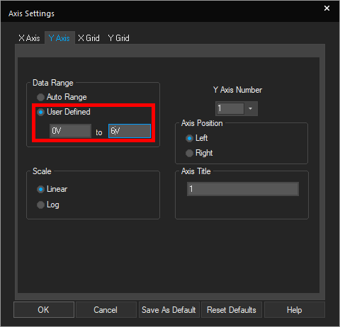
Step 44: Under Data Range, select User Defined and enter 0V for the minimum and 6V for the maximum. Click OK.
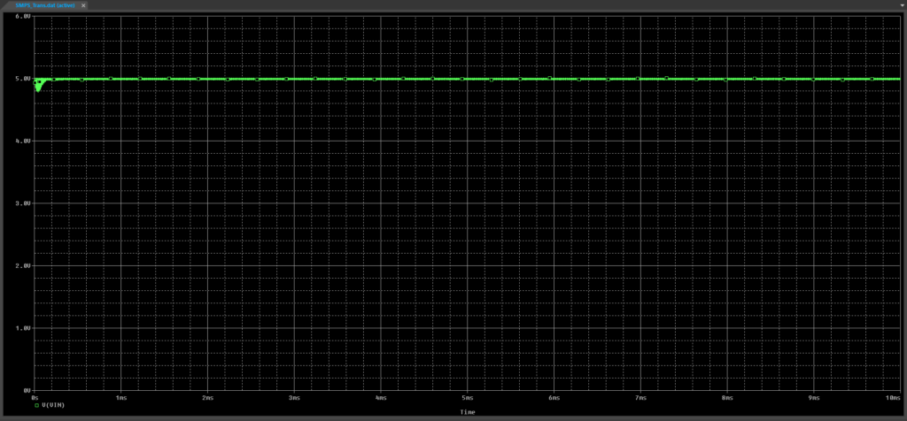
Step 45: View the plotted results. The noise has been filtered out by the ferrite bead and the input voltage holds steady around 5V.
Wrap Up & Next Steps
Quickly create a ferrite bead SPICE model based on datasheet parameters to model accurate circuit behavior and ensure proper noise isolation with PSpice. Test out this feature and more with a free trial of OrCAD. Want to learn more about PSpice? View additional how-tos, walk-throughs, and courses at EMA Academy.

