In an ideal world, the only significant property of an inductor should be its inductance; however, real inductors always have some parasitic resistance and capacitance. Not taking this into account and only simulating ideal inductors may lead to unexpected and undesired circuit behavior. PSpice allows you to quickly define and create a non-ideal inductor SPICE model for a realistic simulation.
This quick how-to will provide step-by-step instructions on how to create a non-ideal inductor SPICE model in OrCAD PSpice.
To follow along, download the provided files above the table of contents.
How-To Video

Running an Ideal Simulation
Step 1: Open the provided design in OrCAD PSpice Designer.
Step 2: Select Place > PSpice Part > Inductor from the menu.
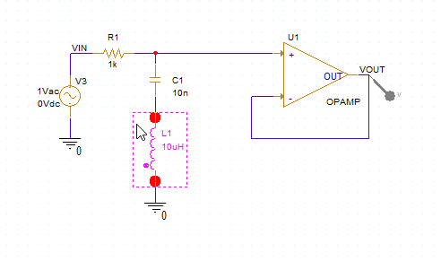
Step 3: Click to place the inductor in the empty space. Right-click and select End Mode.
Step 4: Double-click the value 10uH of the inductor to change it.
Note: This ideal inductor will be used to compare the circuit behavior using an ideal inductor versus a non-ideal inductor.
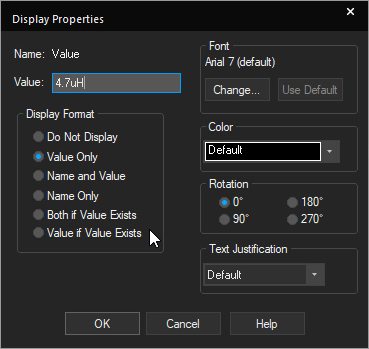
Step 5: Enter a value of 4.7uH and click OK.
Step 6: Select PSpice > Run from the menu.
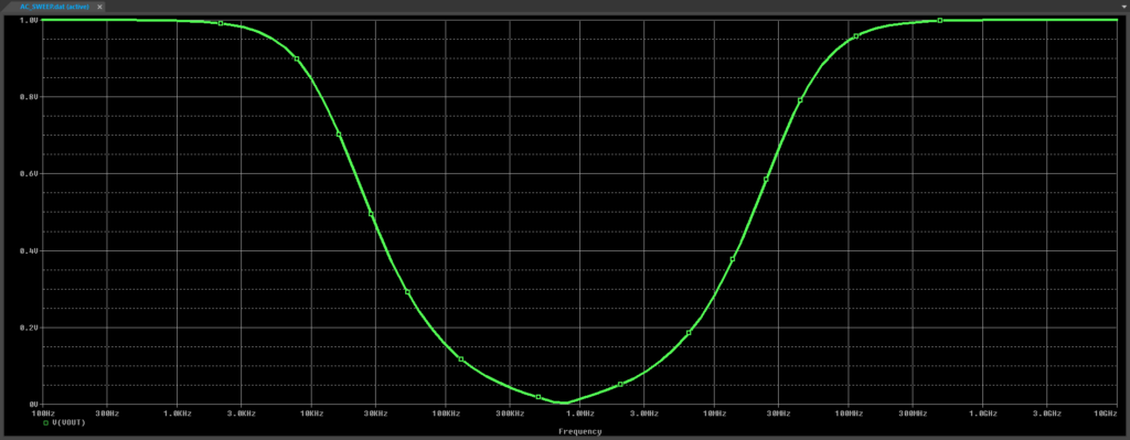
Step 7: View the results. A notch filter plot is shown, as expected. Close the result window.
Creating a Non-Ideal Inductor SPICE Model
Step 8: Back in the schematic, select the inductor and press Delete on the keyboard.
Step 9: Select Place > PSpice Part > Modeling Application from the menu.
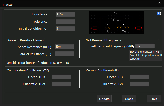
Step 10: Expand Passives and select Inductor. The Inductor window opens.
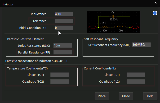
Step 11: Define the following parameters for the non-ideal inductor:
- Inductance: 4.7u
- Initial Condition: 0
- Series Resistance: 10m
- Self-Resonant Frequency: 100MEG
Learn how to determine the required parameters for a non-ideal inductor SPICE Model here.
Note: Additional parameters can be defined including:
- Tolerance
- Parallel resistance
- temperature coefficient
- Current coefficient
Step 12: Click Place to place the inductor.
Step 13: Click to place the part in the empty space.
Step 14: Select PSpice > Run from the menu.
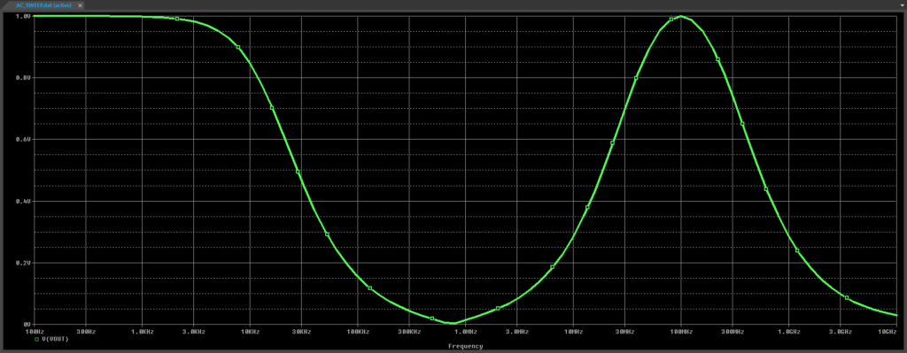
Step 15: View the results. A similar notch filter curve is plotted, but with cutoff above the self-resonant frequency. This is due to the parasitic capacitance of the inductor.
Step 16: Close the result window.
Modifying a Non-Ideal Inductor SPICE Model
Step 17: Back in the schematic, right-click L1 and select More > Edit PSpice Component.
Step 18: Change the self-resonant frequency to 1G. Click Update.
Step 19: Select PSpice > Run from the menu.
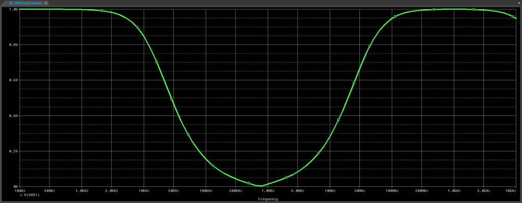
Step 20: View the results. The high-frequency cutoff is now above 1GHz.
Wrap Up and Next Steps
Quickly create the non-ideal inductor SPICE models required to accurately simulate circuit behavior with the Modeling Application in OrCAD PSpice. Test out this feature and more with a free trial of OrCAD. To learn more about determining the required parameters for a non-ideal inductor SPICE Model in your circuit designs, view our blog here.

