Modeling designs helps engineers verify whether their circuit will function as intended. Modeling programs simulate circuit behavior under different conditions and in accordance with the design requirements, allowing engineers to better plan and build circuits.
Typically, to model components, generic models are used, which produce inaccurate and unrealistic simulations based on ideal conditions. This can cause functionality issues to go undetected until far later in the design process. To confidently simulate a component, create a non-ideal inductor SPICE model using specifications from a manufacturer’s datasheet.
What is a Non-Ideal Inductor?
A non-ideal inductor exhibits resonance due to parasitic capacitance.
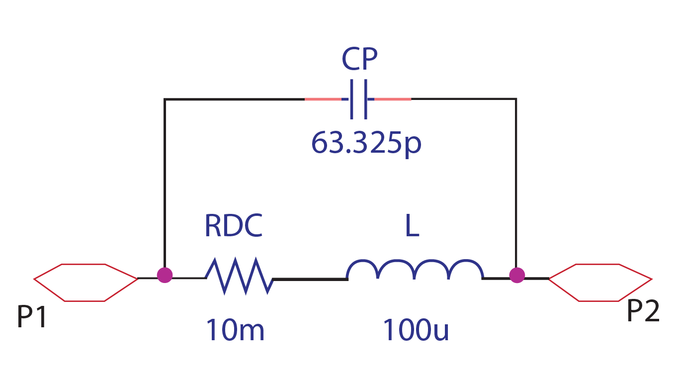
The non-ideal behavior of an inductor is due to the DC resistance of the wire and the self-capacitance. This can be represented in a circuit, with a capacitor in parallel (CP) and a resistance in series (RDC) with the inductor (L).
What is Needed to Model a Non-Ideal Inductor?
Inductor models are frequently used for analog applications, especially those involving a wide range of frequency or high DC currents, such as EMI and DC filters. Often, generic inductor models are used to simulate these designs but in real-life applications, inductors are not ideal. This becomes even more apparent as the frequency used in designs increases; inductors stop functioning like inductors and begin functioning like capacitors. To realistically simulate circuit functionality and create a general-purpose, non-ideal inductor for simulation, there are three items that must be defined:
- Inductance Value
- What is the value of the inductor required for the design?
- DC Resistance
- What is the DC resistance of the wire used to create the inductor?
- Parasitic Capacitance
- An inductor has low distributed capacitance between terminal electrodes or the turns of a wire-wound conductor. What is this self-capacitance for the desired inductor?
The parasitic capacitance (Cp) should be calculated using the following equation:
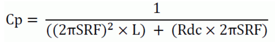
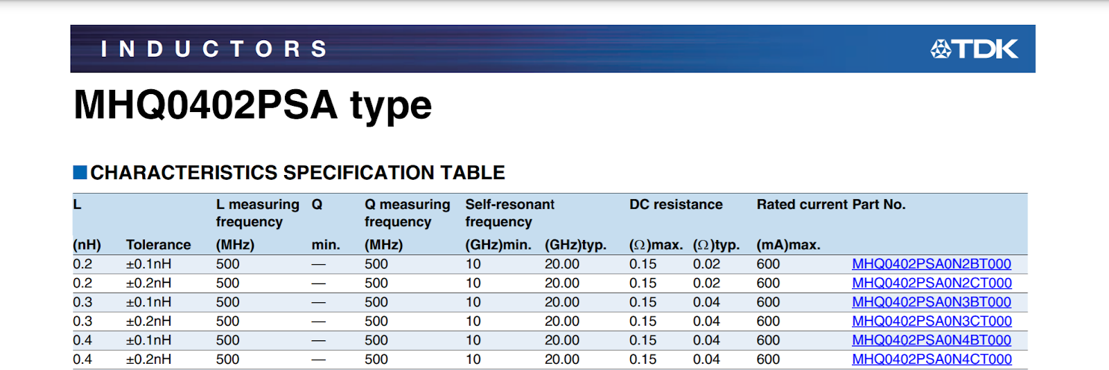
The values for the Self Resonant Frequency (SRF), Inductance (L), and DC Resistance (Rdc) are provided by the manufacturer and often found on the inductor datasheet.
Once this information is obtained and calculated, these values must be incorporated into the SPICE simulation model which can be achieved by manually creating or editing a text file. Keep in mind if the non-ideal inductor created does not produce the intended outcome and a decision is made to change components, values will need to be re-calculated and edited manually. This manual process to produce an accurate inductor model is time consuming and increases the likelihood of errors; however, the PSpice Modeling App provides a fast, easily-configurable, and fully-integrated method to create non-ideal inductors for simulation.
Creating a Non-Ideal Inductor SPICE Model with PSpice
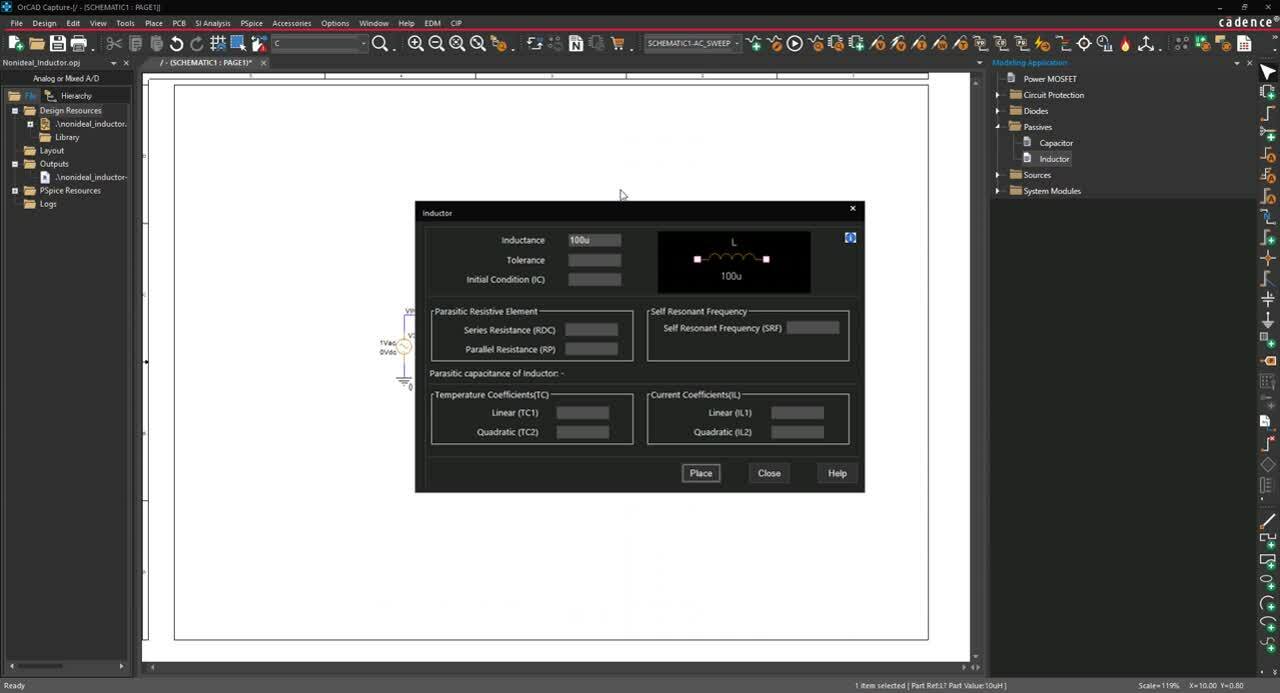
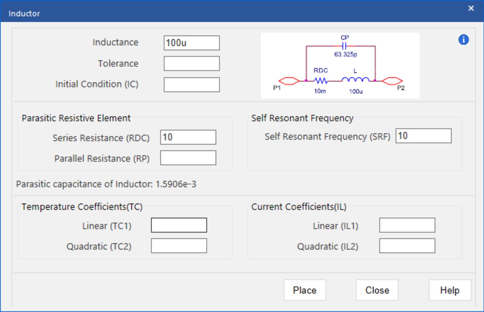
The non-ideal inductor modeling application quickly creates non-ideal inductor SPICE models with a wizard-based approach. To create non-ideal inductor models, users can easily input the inductor characteristics, defined by manufacturers, directly into predefined parameters:
- Inductance (L):
Specify the value of the inductor.
- Self-Resonant Frequency:
Specify the self-resonant frequency. The inductance, with distributed capacitance between terminals or wire-wounds, resonates at a certain frequency. Beyond the resonant frequency, the parasitic capacitance dominates and the inductor behaves like a capacitor.
- Series Resistance: Specify the DC resistance of the wire used to create the inductor.
Rather than calculating the parasitic capacitance by hand, this value is automatically calculated by the modeling application based on the inputted parameters. For a more accurate model and simulation, the modeling application can incorporate additional inductor parameters:
- Tolerance:
The possible variation of the inductor value can be obtained from the manufacturer’s datasheet. The tolerance should be defined as a percentage of the inductance value.
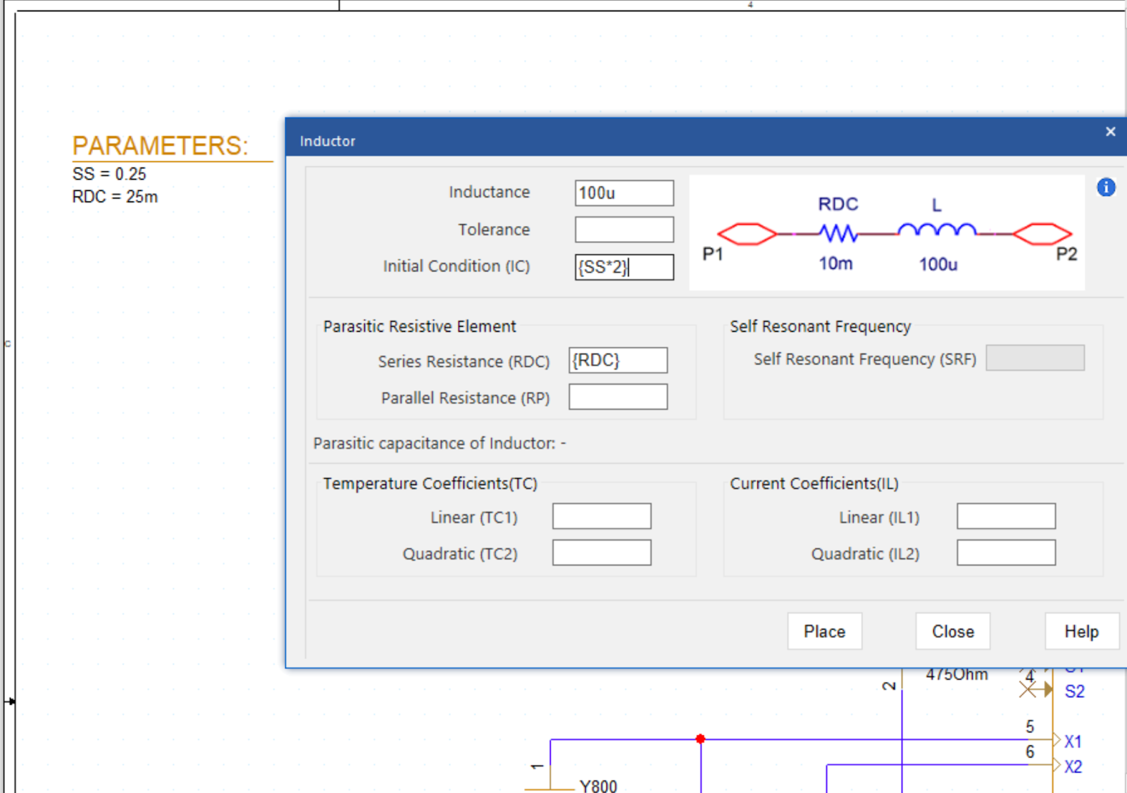
- Initial Condition:
Specify the current through the inductor when time is equal to zero or the simulation begins.
- Parallel Resistor:
Specify the parallel resistance value to model the magnetic loss.
- Linear and Quadratic Temperature Coefficient:
Specify temperature coefficients to model the effects of temperature on the inductor model.
- Linear and Quadratic Current Coefficient:
The modeling application does not include a core model; therefore, the inductor model generated will not demonstrate any saturation characteristics. Specify current coefficients to approximately model the effect of DC current which results in magnetic saturation.
The ease-of-use is amplified with the incorporation of equations into the user-defined parameters. By specifying an equation, rather than a value, the inductor model can be altered without activating the modeling application. Values can be defined and edited directly on the schematic for efficient modeling and simulation.
Using the inputted information above, the PSpice Modeling App generates a schematic symbol and automatically associates the newly created non-ideal inductor SPICE model without leaving the OrCAD Capture environment. The PSpice Modeling App also automatically manages the simulation profile configuration, eliminating any library set up for simulation. Be sure to check out additional SPICE model how-tos and download the Free Trial of OrCAD to try it yourself.
For step-by-step instructions on creating a non-ideal inductor SPICE model, view our how-to.