High-power diodes are critical in applications such as automotive alternator power rectification and power grid inverters, among many others. In these applications, it is important to accurately analyze circuit behavior to ensure functionality, safety, and reliability. PSpice allows you to quickly define and create a power diode SPICE model to produce a realistic simulation.
This quick how-to will provide step-by-step instructions on how to create a power diode SPICE model in OrCAD PSpice.
To follow along, download the provided files above the table of contents.
How-To Video

Creating a Power Diode SPICE Model
Step 1: Open the provided design in OrCAD PSpice Designer.
Step 2: Select Place > PSpice Part > Modeling Application from the menu.
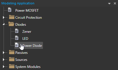
Step 3: In the Modeling Application, expand Diodes and select Power Diode.
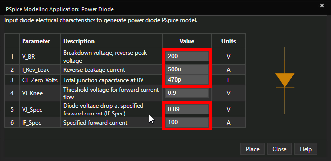
Step 4: The Power Diode window opens. Set the following parameters
- Breakdown Voltage: 200
- Reverse Leakage Current: 500u
- Total Junction Capacitance at 0V: 470p
- Forward Voltage Drop: 0.89
- Specified Forward Current: 100
Learn how to decipher a power diode datasheet to determine the parameters required for SPICE Model creation here.
Note: A threshold voltage for forward current can be set as well.
Step 5: Click Place to attach the diode to your cursor.
Step 6: Click to place the diode in one of the empty spaces in the schematic.
Step 7: With the diode selected, press CTRL-C on the keyboard to copy and CTRL-V to paste.
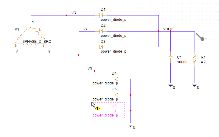
Step 8: Click to place five more instances of the diode in the circuit to create a three-phase full bridge rectifier.
Note: Press R on the keyboard to rotate a placed diode.
Running the Simulation
Step 9: Select PSpice > Run from the menu.
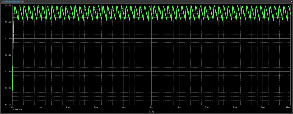
Step 10: View the simulation results. A rectified signal is shown, as expected.
Modifying the Power Diode SPICE Model
Step 11: Back in the schematic, select each diode and press Delete on the keyboard.
Note: Hold CTRL on the keyboard to select multiple components.
Step 12: Back in the Modeling Application, select Diodes > Power Diode.
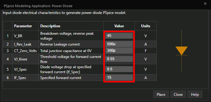
Step 13: Set the following parameters:
- Reverse Breakdown Voltage:45
- Reverse Leakage Current: 500u
- Threshold Voltage: 0.55
- Forward Voltage Drop: 0.5
- Specified Forward Current: 15
Note: This information can be obtained from a diode’s datasheet.
Step 14: Click Place to attach the diode to your cursor.
Step 15: Click to place the diode.
Step 16: With the newly placed diode selected, press CTRL-C on the keyboard to copy and CTRL-V to paste. Placefive additional instances of the diode in the circuit as before.
Step 17: Select PSpice > Run from the menu.
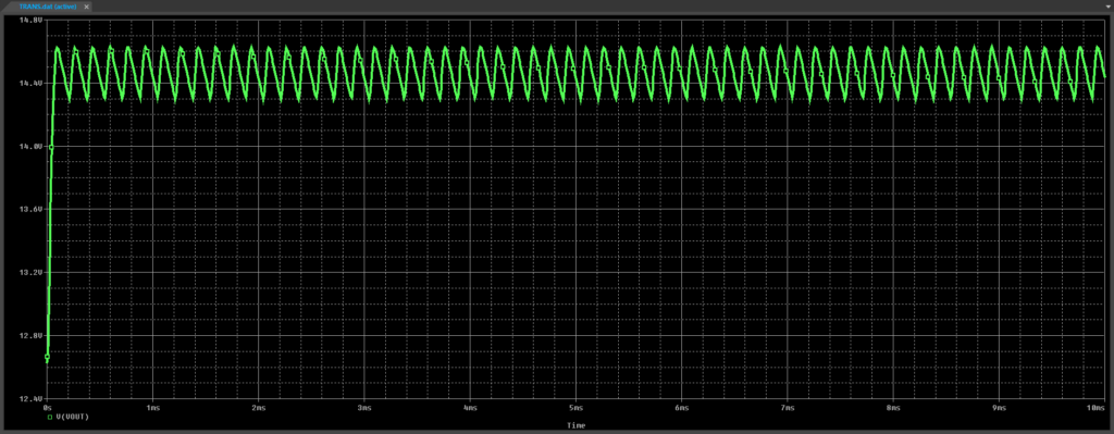
Step 18: View the simulation results. The average rectified voltage is higher due to the lower voltage drop, but the ripple is higher as well due to the associated heavier load.
Wrap Up and Next Steps
Quickly create the required power diode SPICE models and simulate accurate circuit behavior with the modeling application in OrCAD PSpice. Test out this feature and more with a free trial of OrCAD. To learn more about deciphering a power diode datasheet to determine the parameters required for SPICE Model creation, view our blog here.

