Modeling designs help engineers verify whether their circuit will function as intended. Modeling programs simulate circuit behavior under different conditions and in accordance with the design requirements, allowing engineers to better plan and build circuits.
Typically, to model components, generic models are used, which produce inaccurate and unrealistic simulations based on ideal conditions. This can cause functionality issues to go undetected until far later in the design process. To confidently simulate a component, a power diode SPICE model should be created using specifications from the manufacturer’s datasheet.
What is a Power Diode?
A power diode is a two terminal device consisting of an anode and cathode that conducts current in one direction. Power diodes are commonly used in power circuits and differ in construction compared to standard diodes in order to meet the demands of high-power applications.
What is Needed to Model a Power Diode?
To create the required power diode for simulation, the device parameters must be obtained from the manufacturer’s datasheet:
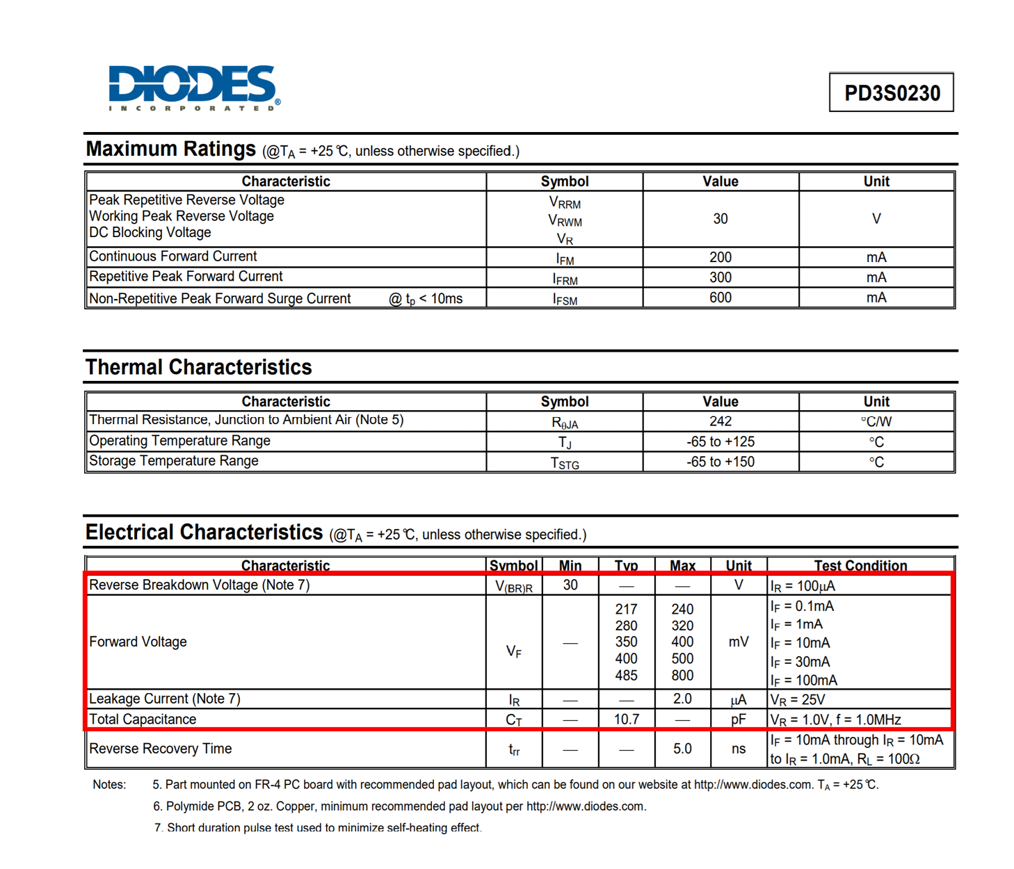
- Electrical Characteristics
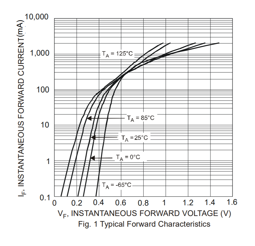
- What are the critical electrical characteristics of the power diode: reverse breakdown voltage, forward voltage, etc.?
Once this information is obtained, these values must be incorporated into the SPICE simulation model which can be achieved by manually creating or editing a text file. Keep in mind if the power diode created does not produce the intended outcome and a decision is made to change components, values will need to be edited manually. This manual process to produce an accurate power diode model is time consuming and increases the likelihood of errors; however, the PSpice Modeling App provides a fast, easily-configurable, and fully-integrated method to create power diodes for simulation.
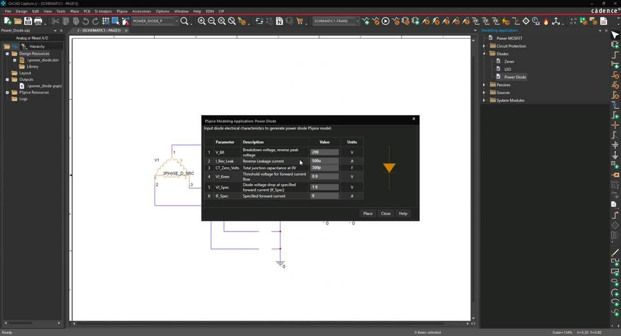
Creating a Power Diode SPICE Model with PSpice
The Power Diode modeling application quickly creates power diode models with a wizard-based approach. The parameterized diode enables simulation and testing of the model in various conditions. The necessary specifications are predefined and users can easily input the power diode characteristics, defined by manufacturers, directly into the parameters:
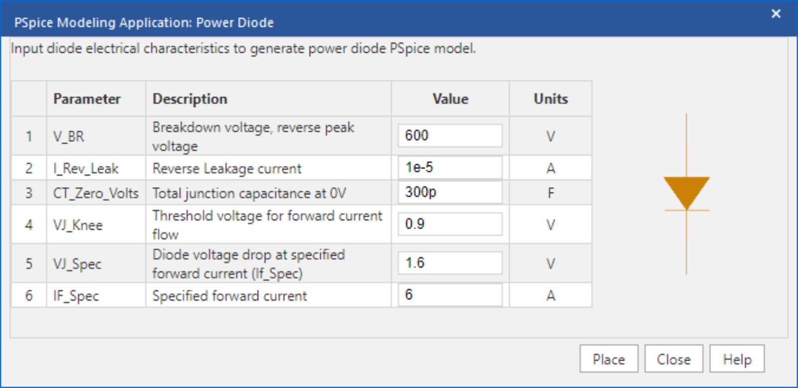
- Breakdown Voltage: Define the reverse peak voltage across the diode (V_BR).
- This value must be between 3V and 5kV. This is commonly referred to as the Reverse Breakdown Voltage (Vbr) or the Repetitive Peak Reverse Voltage (Vrrm) on manufacturer’s datasheets.
- Reverse Leakage Current: Define the reverse leakage current when the diode is reverse biased (I_Rev_Leak).
- This value must be between 1nA and 500uA. This is commonly referred to as Reverse Leakage Current (Ir) on manufacturer’s datasheets.
- Total Junction Capacitance: Define the total junction capacitance across the diode at 0V (CT_Zero_Volts).
- This value must be between 0 and 100nF. This is commonly referred to as the Total Capacitance (Ct) on manufacturer’s datasheets.
- Threshold Voltage: Define the forward bias voltage required for the diode to start conducting.
- The threshold voltage (VJ_Knee) value must be between 0.4V and 5V. This is commonly referred to as the knee voltage.
- Voltage/Current Characteristics: Define a voltage and current data point pair.
- Voltage Drop: Define the diode voltage drop at the specified forward current.
- The value of the voltage drop (VJ_Spec) must be between 0.5V and 7V. 2.
- Specified Forward Current: Define the specified forward current for the voltage/current data point pair.
- The specified forward current (IF_Spec) must be between 10uA and 1kA.
Using the inputted information above, the PSpice Modeling App generates a schematic symbol and automatically associates the newly created power diode SPICE model without leaving the OrCAD Capture environment. The PSpice Modeling App also automatically manages the simulation profile configuration, eliminating any library set up for simulation. To try this yourself, be sure to download the Free Trial of OrCAD and check back for additional SPICE model how-tos.
For step-by-step instructions on creating a power diode SPICE model, view our how-to.


