Modeling designs helps engineers verify whether their circuit will function as intended. Modeling programs simulate circuit behavior under different conditions and in accordance with the design requirements, allowing engineers to better plan and build circuits.
Typically, to model components, generic models are used, which produce inaccurate and unrealistic simulations based on ideal conditions. This can cause functionality issues to go undetected until far later in the design process. To confidently simulate a component, create a non-ideal capacitor SPICE model using specifications from a manufacturer’s datasheet.
What is a Non-Ideal Capacitor?
Non-Ideal capacitor models incorporate resistive and inductive parasitics.
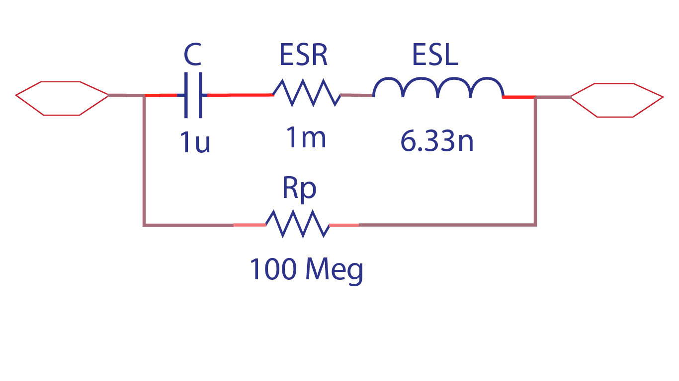
The non-ideal behavior of a capacitor is due to imperfections within the capacitor’s material that create resistance causing the capacitor to dissipate energy. This can be represented in a circuit with a resistor in parallel (RP) as well as a resistance (ESR) and inductance (ESL) in series with the capacitor (C).
What is Needed to Model a Non-Ideal Capacitor?
Generic capacitor models are often used to quickly simulate designs, but in real-life applications, capacitors are not ideal. This becomes even more apparent as the frequency used in designs increases; inductance is increased along with the frequency, canceling the capacitance. To realistically simulate circuit functionality and create a non-ideal capacitor for simulation, there are four items that must be defined:
- Capacitance Value
- What is the value of the capacitor required for the design?
- Series Resistance
- What is the resistance caused by the capacitor’s materials?
- Parasitic Inductance
- What is the inductance caused by the capacitor’s leads?
- Dissipation Factor
- What amount of power is lost through the capacitor?
Once this information is obtained or calculated, these values must be incorporated into the SPICE simulation model which can be achieved by manually creating or editing a text file. Keep in mind if the non-ideal capacitor created does not produce the intended outcome and a decision is made to change components, values will need to be re-calculated and edited manually. This manual process to produce an accurate capacitor model is time consuming and increases the likelihood of errors; however, the PSpice Modeling App provides a fast, easily-configurable, and fully-integrated method to create a non-ideal capacitor SPICE Model for simulation.
Creating a Non-Ideal Capacitor SPICE Model with PSpice
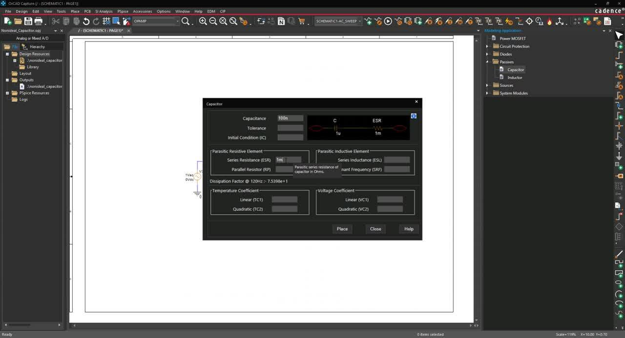
The non-ideal capacitor modeling application quickly creates non-ideal capacitor SPICE models with a wizard-based approach. To create non-ideal capacitor models, users can easily input the capacitor characteristics, defined by manufacturers, directly into predefined parameters:
Capacitance (C)
Specify the value of the capacitor.
Series Resistance (ESR) and Dissipation Factor
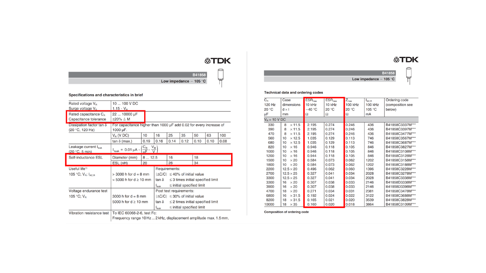
Specify the Equivalent Series Resistance (ESR) to add resistance in series. By defining this parameter, the modeling application automatically calculates the dissipation factor. The dissipation factor is the power loss through the capacitor which is either absorbed by the dielectric material or the internal/external resistance and is calculated by dividing the equivalent series resistance by the capacitive reactance.
Parasitic Inductive Element
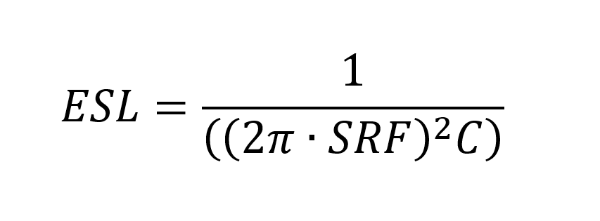
To model the parasitic inductance, an equivalent series inductance (ESL) is placed in series with the capacitor model. Typically, manufacturers only provide one of the required values: either Series Inductance or Self-Resonant Frequency.
- Series Inductance (ESL):
Specify the equivalent series inductance.
- Self-Resonant Frequency (SRF):
Specify the self-resonant frequency. This is the frequency where the capacitance is canceled by the inductance and is often defined by the manufacturer.
The modeling application only requires one of these values to be defined, then automatically calculates the other to determine the parasitic inductive element using the following equation:
For a more accurate model and simulation, the modeling application can incorporate additional capacitor parameters:
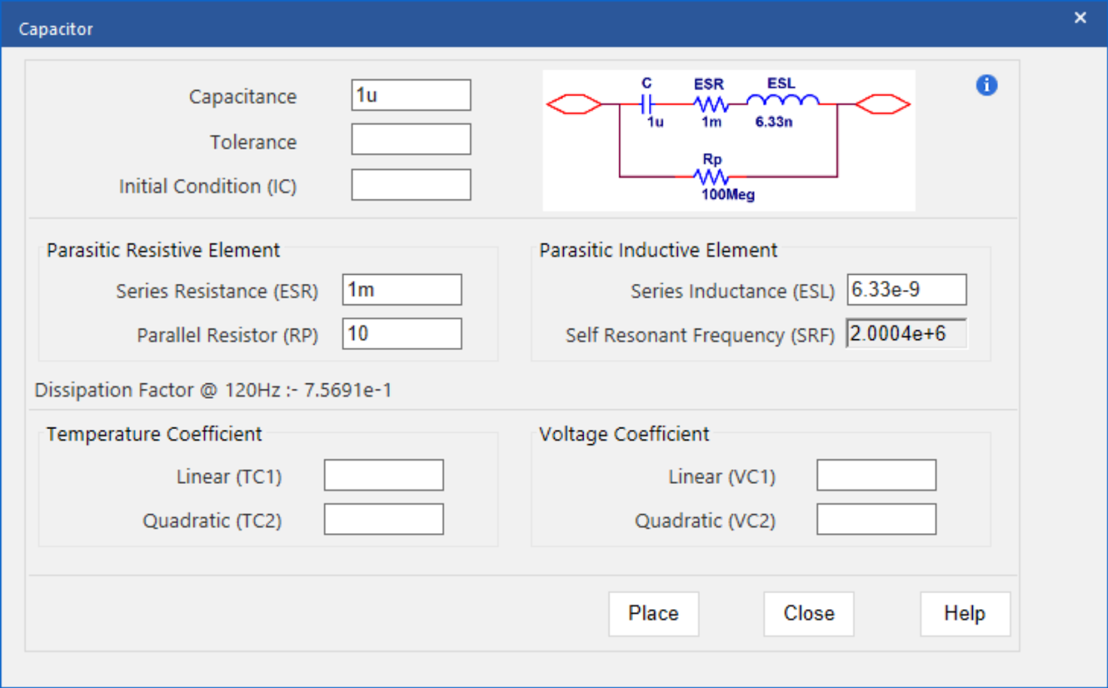
- Tolerance:
The possible variation of the capacitor value can be obtained from the manufacturer’s datasheet. The tolerance should be defined as a percentage of the capacitance value.
- Initial Condition:
Specify the voltage across the capacitor when time is equal to zero or the simulation begins. Typically, this can be obtained from the manufacturer’s datasheet.
- Parallel Resistor:
Specify the parallel resistance value to model the DC leakage current. Leakage current occurs when conductors are not separated by a perfect dielectric and the material has a small conductivity.
- Linear and Quadratic Temperature Coefficient:
Specify temperature coefficients to model the effects of temperature on the capacitor model.
- Linear and Quadratic Voltage Coefficient:
Specify voltage coefficients to approximately model the effect of DC voltage which results in a decrease in capacitance.
The ease-of-use is amplified with the incorporation of equations into the user-defined parameters. By specifying an equation, rather than a value, the capacitor model can be altered without activating the modeling application. Values can be defined and edited directly on the schematic for efficient modeling and simulation. Learn what parameters are required to create a non-ideal inductor SPICE model here.
To try this yourself, be sure to download the Free Trial of OrCAD and for step-by-step instructions on how to create a non-ideal capacitor SPICE model, check out our how-to.


