Modern electronics often have strict requirements for copper pours to meet power and ground requirements, avoid impedance issues, and improve signal integrity. The ability to freeze and unfreeze copper shapes helps designers make modifications while preserving shape integrity. With OrCAD, you can create:
- Dynamic Shapes: Update automatically for voiding and healing.
- Static Shapes: Do not update. Any voiding must be done manually.
- Frozen Shapes: Dynamic shapes are frozen and can be updated after design modifications.
This quick how-to will provide step-by-step instructions on how to lock or freeze copper shapes in OrCAD PCB Designer.
How-To Video
 Open in New Window
Viewing Shape Capabilities
Note: There are many options for shape creation in OrCAD.
Step 1: Open in a design in OrCAD PCB Designer Professional.
Step 2: Select the Add Rectangle button from the toolbar.
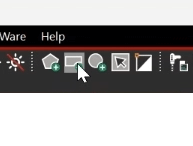
Step 3: Select the Options tab to view the shape options.
Step 4: Open the Type dropdown. Options are available to create:
- Dynamic Copper
- Dynamic Crosshatch
- Static Solid
- Static Crosshatch
Note: Need help with Copper Shapes and Planes? View our free quick tutorial here.
Viewing Dynamic Healing
Routing in OrCAD PCB
Step 5: Select Route > Connect from the menu or the Add Connect button from the toolbar.
Note: If needed, adjust visibility to see the copper pours. Select the Visibility tab and enable visibility for the GND or VCC plane layer as desired.
Step 6: Click to start drawing a trace on another layer of the board.
Step 7: Double-click to add a via. Select the destination layer and click OK.
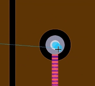
Step 8: View the copper plane. A void is automatically created to accommodate the via.
Step 9: Right-click and select Cancel.
Freezing a Copper Shape
Step 10: Select Shape > Freeze Shape from the menu.
Step 11: Select the desired shape to freeze. The Command window will notify you that the shape has been frozen.
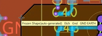
Step 12: Hover over the shape. A tooltip appears that the shape is frozen.
Note: For improved selection, select Shapes in the Find panel if it is not already checked.
Step 13: Select Route > Connect from the menu or the Add Connect button from the toolbar.
Step 14: Click to route a trace or group of traces on a different layer. Double-click to place a via, select the destination layer, and click OK.
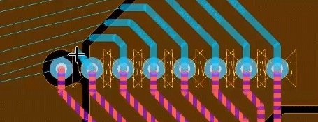
Step 15: Click to place the vias. Any vias placed within the boundaries of unfrozen shapes will create voids, but vias placed within frozen shapes will not.
Note: DRC errors will be created for the vias placed in the frozen shape.
Step 16: Right-click and select Done.
Unfreezing a Shape
Step 17: Select Shape > Unfreeze Shape from the menu.
Step 18: Select the shape to unfreeze. Right-click and select Done.
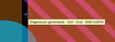
Step 19: Hover over the shape. The normal shape tooltip appears.
Step 20: Select Check > Design Status from the menu.
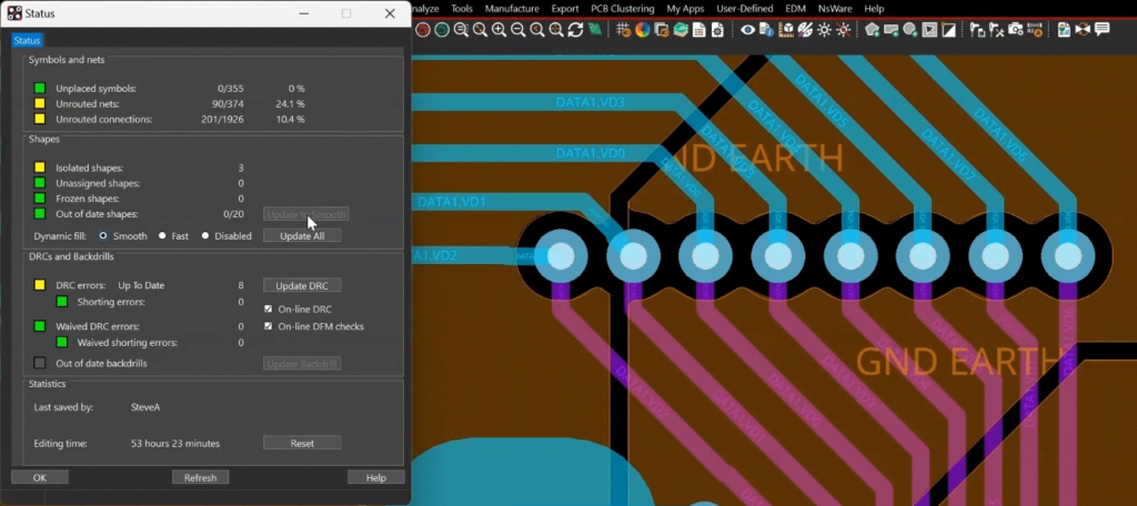
Step 21: In the Status window, under Shapes, select Update to Smooth. Voids are automatically created for any vias placed in the shape and the DRC errors are removed.
Wrap Up & Next Steps
Quickly and easily freeze copper shapes to preserve the integrity of copper planes and pours with the new freeze and unfreeze capabilities in OrCAD PCB Designer. Upgrade to 23.1 to test out this and other new features in OrCAD.

