One of the final steps in the PCB design process is generating the required manufacturing data to fabricate and assemble the design. Post processing a design by determining and creating all the required documentation can be time-consuming, especially when manufacturing requirements differ and multiple board revisions are required based on manufacturing feedback. Easily configure the required files and automatically generate a manufacturing output from a centralized location with Post Processing in OrCAD Productivity Toolbox and OrCAD PCB Designer. With Post Processing, users can:
- Configure jobs based on manufacturing requirements
- Quickly generate the selected manufacturing outputs
- Standardize manufacturing outputs between revisions and for entire teams
- Save time documenting the design
This quick how-to will provide step-by-step instructions on how to use the Post Processing function in OrCAD PCB Designer to automate the generation of manufacturing documentation.
To follow along, download the provided files above the table of contents.
How-To Video
Creating a Post-Processing Job
Step 1: Open the provided design, Post-Proc.brd,in OrCAD PCB Designer Professional with the OrCAD Productivity Toolbox option selected.
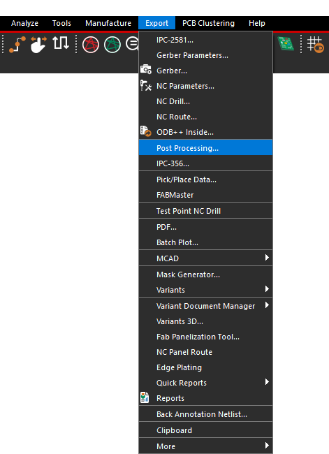
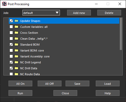
Step 2: Select Export > Post Processing from the menu.
Step 3: Under Job, select Add New.
Note: A job contains multiple tasks which are executed sequentially. Jobs can be created for varying manufacturers or functions and can be easily reused to expedite post-processing.
Step 4: Name the job Manufacturing1 and click OK.
Configuring the Post-Processing Output
Step 5: Select the tasks to be included in the post-processing job. Configure the following selection:
- Cross Section
- Standard BOM
- NC Route Data
- PDF Export
Note: The following options are available:
- Update Shapes: Update all dynamic shapes in the design. This is typically the first step before creating data.
- Cross Section: Generate a cross section drawing for documentation purposes.
- Clean Data: Performs delete operations based on provided arguments to clean directories before new data is generated.
- Standard BOM: Generate a Bill of Material in csv and text format.
- Variant BOM: Core: Generates a variant BOM report.
- Variant Assembly: Core: Generates variant assembly drawings.
- Drawing Designer: Updates all drawing items such as scaled views.
- Drawing View Manager: Updates all drawing view items.
- NC Drill Legend: Updates drill legends and drill charts in the design.
- NC Drill Data: Generates NC drill data, such as drill charts, for the design.
- Artwork Data: Generates and processes all artwork data for the design.
- PDF Export: Generates a combined PDF for all artwork records in the design.
- Batch Plot: Generates PDF data according to module “BatchPlot.”
- Mfg Collector: Collects data using file copy/move/rename operations.
- Zip Data: Generates Zip data. Requires arguments for the name of the file and items to be zipped.
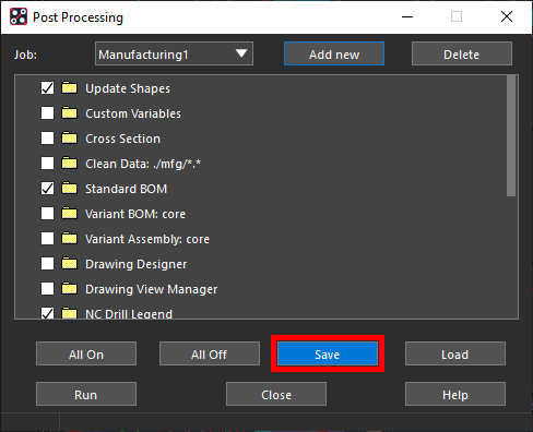
Step 6: Select Save to save the list of selected options.
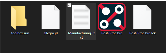
Step 7: Save the list as Manufacturing1.txt.
Note: Users can easily load the saved job file to save time and create consistency for teams. This file can be viewed in a text editor from the working directory.
Performing Post-Processing
Step 8: Select Run to generate the post-processing files.
Note: Several tasks, such as Artwork and NC Drill generation, need to be pre-configured to complete post-processing. To do so, switch to the configuration tab to configure the corresponding task.
The tasks, or selected post-processing items, are executed sequentially and files are saved in the working directory.
Step 9: Click Close to close the window.
Reviewing Post-Processing Data
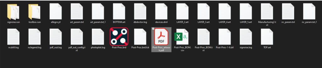
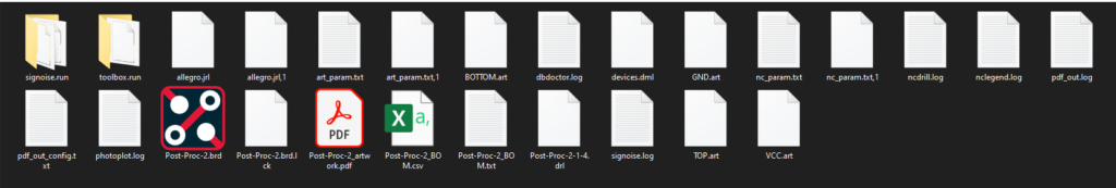
Step 10: Open File Explorer and browse to the working directory for Post-Proc.brd.
Step 11: Open Post-Proc-artwork.pdf in a PDF viewer of your choice.
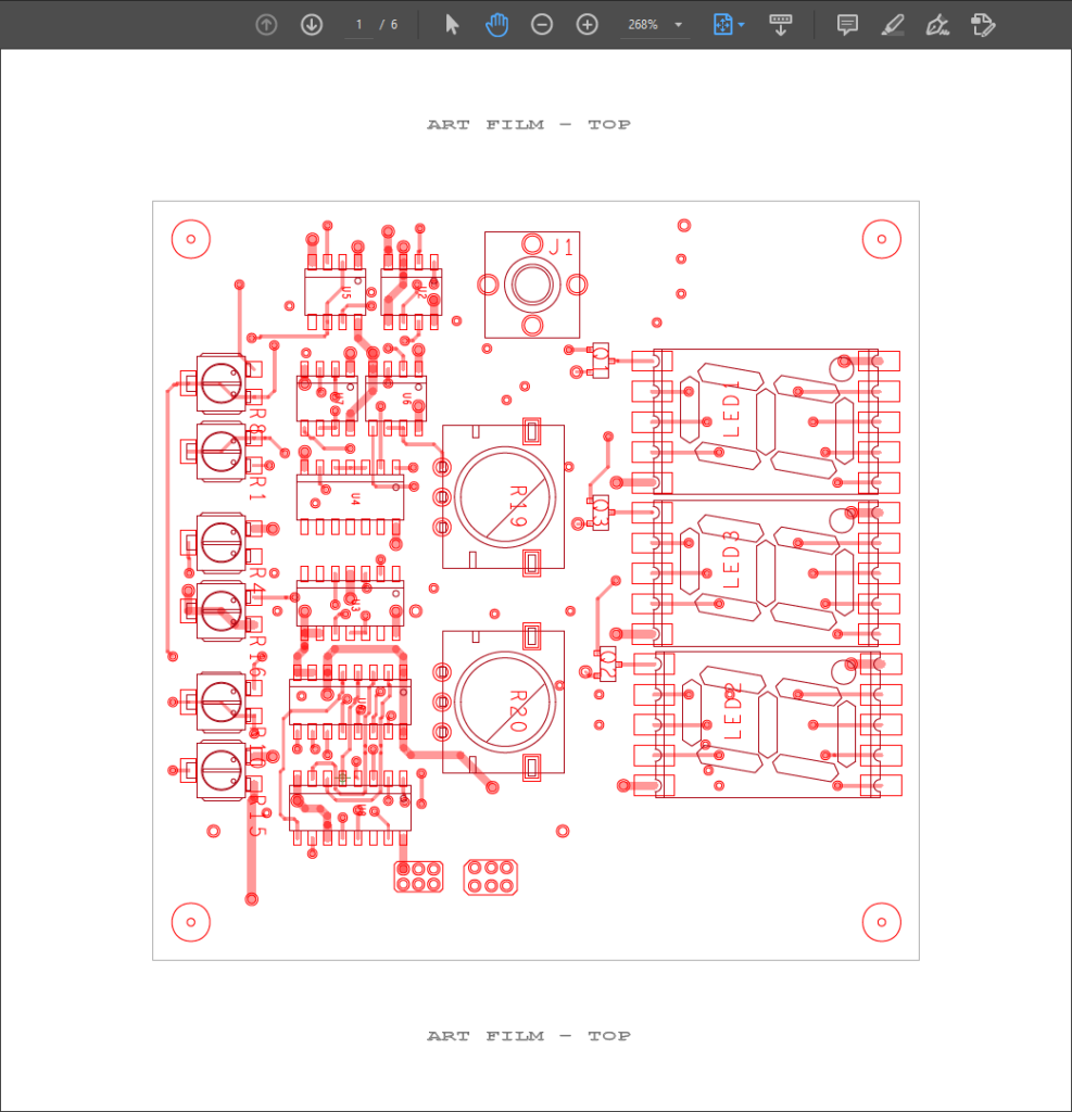
Step 12: Scroll through the PDF file. Each page is a visual representation of the art film for layers in the design. This file was generated with the PDF Export option. Close the PDF viewer.
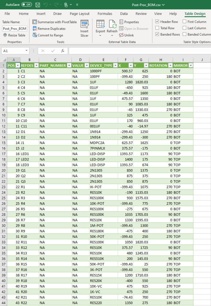
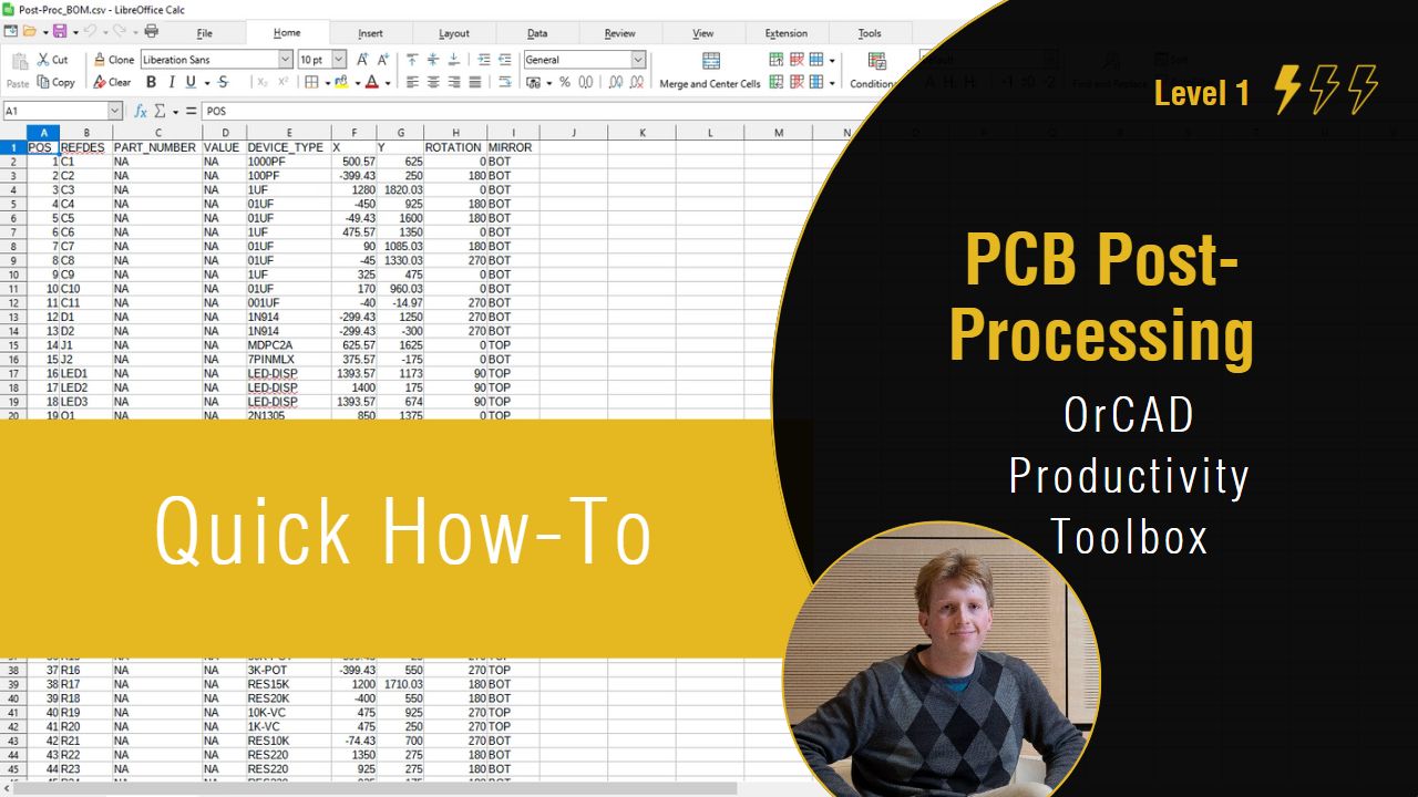
Step 13: Open Post-Proc_BOM.csv in a spreadsheet viewer of your choice (e.g. Microsoft Excel or LibreOffice Calc).
Note: The CSV data exported is separated by semicolons, not commas. In North America, the standard Excel separator is commas. To load the file in Excel, perform the following steps.
Step 1: Open a blank workbook.
Step 2: Select the Data tab and select From Text/CSV.
Step 3: Browse to the CSV file and select Import.
Step 4: Select Semicolon from the Delimiter dropdown and click Load. The file is loaded.
If loading the file in LibreOffice Calc, a similar import window is shown to specify semicolon as the delimiter.
Step 14: This file is generated with the Standard BOM option and lists all parts on the board with their location, layer, and rotation. Close the CSV file.
Note: A variant BOM can also be generated if the design uses variant components.
Reusing the Post-Processing Settings
Step 15: Open the provided design, Post-Proc-2.brd, in the same runtime of OrCAD PCB Designer.
Step 16: Select Export > Post Processing from the menu.
Note: The selected options have reverted back to the defaults.
Step 17: Select Load to load in an options preset.
Step 18: Browse to the location of the saved Manufacturing1.txt file to load the file. The Cross Section and NC Route Data options were selected automatically.
Step 19: Select Run to generate the post-processing files. Browse to the working directory in File Explorer and view the files.
Wrap Up & Next Steps
Efficiently generate the correct manufacturing data and streamline the documentation process with Post Processing in OrCAD Productivity Toolbox. To learn more about how the features of OrCAD Productivity Toolbox can expedite your PCB designs, view our latest webinar.

