Defining every component in a large schematic design can be tedious and time-consuming. To streamline this process, OrCAD X Capture stores all components in a design in the design cache. The design cache in OrCAD X Capture can be used to:
- Quickly place components which are already used in the schematic to maintain consistency and save time
- Easily locate and replace components in the design to manage change orders
This quick how-to will provide step-by-step instructions on how to keep your design up to date and organized by using the design cache in OrCAD X Capture.
To follow along, download the provided files above the table of contents.
How-To Video
 Open in New Window
Opening the Design Cache in OrCAD X Capture
Step 1: Open the provided design in OrCAD X Capture.
Step 2: In the Project Manager, expand the design folder under Design Resources. Two folders, SCHEMATIC1 and Design Cache are shown.
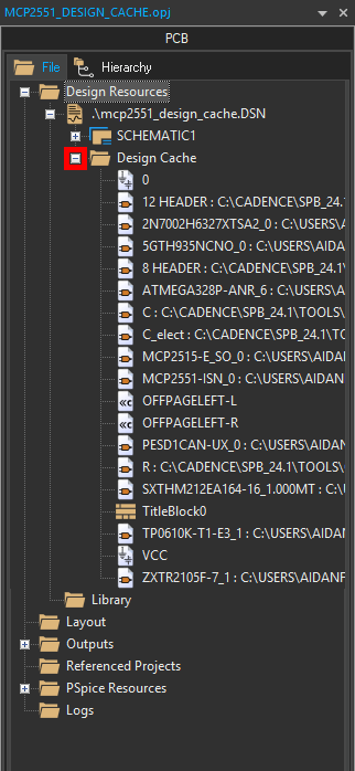
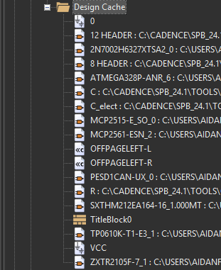
Step 3: Expand Design Cache to view the existing design cache.
Note: The cache contains an alphabetized list of all parts currently in the design and their library source.
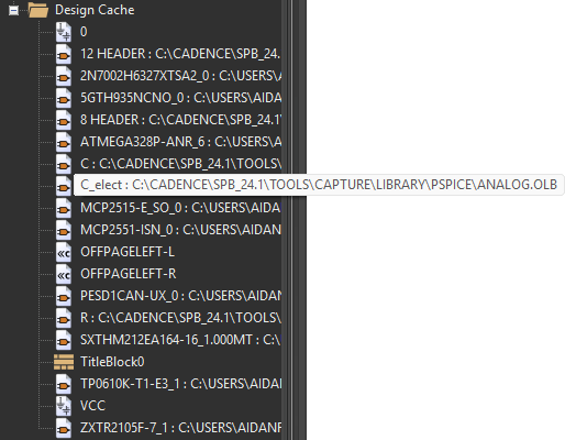
Step 4: Hover over C_elect in the design cache list to view its library path. The path is shown as the default C:\Cadence\SPB_24.1\tools\capture\library\pspice\analog.olb.
Locating a Part in the Design Cache
Step 5: In this example design, we will replace the MCP2551 CAN transceivers with newer MCP2561 transceivers. Right-click MCP2551 in the Design Cache and select Part Manager.
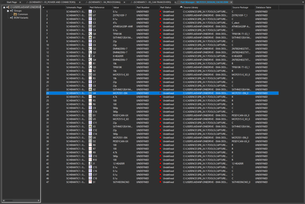
Step 6: The Part Manager tab opens, showing a list of all symbols present in the design and their source libraries. Select U4, one of two MCP2551s in the design.
Step 7: Right-click the listing and select Goto Part on Schematic. The view pans to the schematic page with the MCP2551s on it and U4 is highlighted.
Step 8: Close the Part Manager tab.
Replacing a Part from the Design Cache
Step 9: The design cache can be used to replace all instances of a part in the design at once. Right-click MCP2551 in the design cache and select Replace Cache.
Step 10: A warning appears, stating that replacing a cached part will clear the undo/redo cache for the current session. Click Yes to proceed.
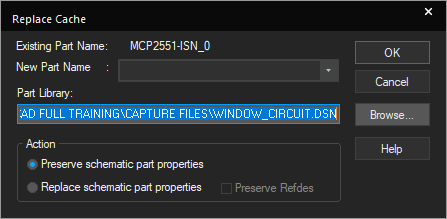
Step 11: The Replace Cache window opens. Here you can select the library and name for the new part. Select Browse to browse for a library.
Step 12: Browse to and select the provided MCP2561-E-SN.OLB library file. Click Open.
Step 13: Select MCP2561-ESN from the New Part Name dropdown.
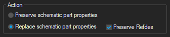
Step 14: Under Action, select Replace Schematic Part Properties to ensure the part is completely refreshed. Check Preserve Refdes to preserve the reference designator.
Step 15: Click OK. If prompted to save the design, click Yes to proceed.
Adjusting a Replacement Part
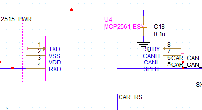
Step 16: The MCP2551s in the design are refreshed with new MCP2561s with different schematic symbols, which no longer fit. To adjust the symbols, select one of the MCP2561s and right-click and select Edit Part.
Step 17: The Part Editor tab opens. Select the outline. Click and drag one of the corners to adjust the symbol to be 8 units wide and 10 units tall.
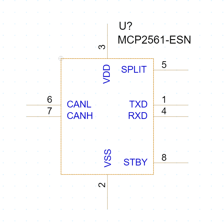
Step 18: Click and drag the pins to arrange them as shown above.
Step 19: Close the Part Editor tab. When prompted, select Update All to update both MCP2561s in the design.
Step 20: When prompted, click Yes to save the design and Yes again to clear the undo/redo cache.
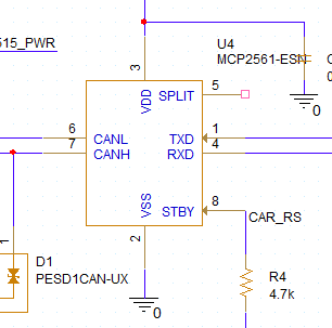
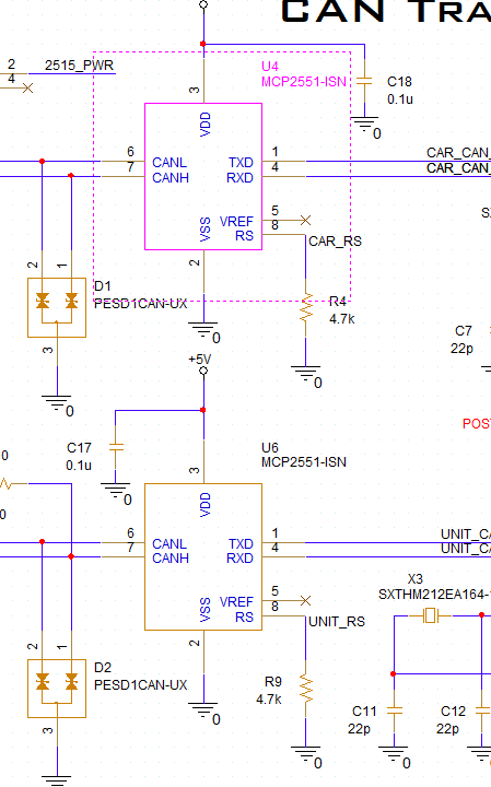
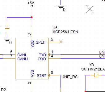
Step 21: View U4 and U6 in the schematic canvas. All nets connected properly and the IC symbols fit much better.
Step 22: Pin 5, which is unconnected in the design, must be designated as no-connect. Select Place > No-Connect from the menu.
Step 23: Click to place no-connects on pin 5 (SPLIT) of both MCP2561s. Right-click and select End Mode when finished.
Note: On the MCP2561, this pin is used as a reference for CAN bus voltage. In this design, the reference is unused, so the pin does not need to be connected.
Placing a Part from the Design Cache in OrCAD
Step 24: Instances of a common part can also be placed from the design cache. For this example, we will replace switch S1 with a jumper resistor as the circuit it powers does not need to be momentary. Select S1 and press Delete on the keyboard.
Step 25: Select Place > Part from the menu.
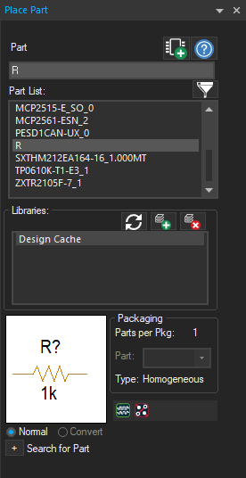
Step 26: The Place Part panel opens with the Design Cache library selected. Select R from the Part List.
Step 27: Select Place Part to attach the part to your cursor.
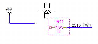
Step 28: Click to place the resistor on the 2515_PWR net. Right-click and select End Mode.
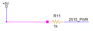
Step 29: Click and drag the end of the floating +5V net to connect it to the other side of the new resistor.
Step 30: Double-click the resistor value to change it. Enter 0 to create a low-resistance jumper and click OK.
Clearing the Design Cache in OrCAD
Step 31: Parts who no longer have instances on the schematic should be removed from the design cache to ensure the design file does not get too large. Select the Design Cache folder in the Project Manager.
Step 32: Right-click the folder and select Cleanup Cache. Click Yes when prompted to clear the undo/redo cache and save the design.
The 5GTH935NC switch is removed from the design cache.
Wrap Up & Next Steps
Quickly and easily find used components, change components, and keep designs organized with the design cache in OrCAD X Capture. Test out this feature and more with a free trial of OrCAD. Want to learn more about Capture? Get access to free how-tos, courses, and walk-throughs at EMA Academy.

