Company: EK Power Solutions | Industry: Power Electronics | Solution: OrCAD X
“When we are thinking about what is best for the customer in the long run, the answer is that we need to push the organization forward and align us with the customer’s needs. Using OrCAD Capture CIS helps us to accomplish this and deliver high-quality PCB layouts.”
Vidar Wernöe, CEO, EK Power Solutions
About EK Power Solutions
Founded in 1978, EK Power Solutions is a leading Nordic design house specializing in power electronics and printed circuit board layouts. Based just north of Stockholm, the ISO-certified company delivers custom design solutions for power supplies, motor drives, frequency converters, battery charging systems, and PCB layouts.
Goals
EK Power Solutions aimed to strengthen collaboration with customers involved in complex, high-tech product development. As client demands increased for tighter integration, better data consistency, and improved mechanical alignment, the company sought a scalable PCB design solution that would support long-term partnerships while maintaining high reliability and quality standards.
Challenges
EK Power Solutions executes 60-100 project assignments of various sizes each year for clients including automation, telecommunications, power generation, medical technology, railway, marine, automotive and defense sectors. This presents many design challenges that EK Power Solutions needed to overcome, including:
Design Compatibility
While EK Power Solutions focuses on in-house projects, they also perform requested layout work for external clients. Operating across numerous client environments meant managing PCB layouts created in multiple CAD systems, complicating maintenance and updates.
Design Complexity and Mechanical Restrictions
Existing designs often exceeded the capabilities of prior tools and limited 3D integration created friction with mechanical design teams. This resulted in designs which were hard to manage and verify and increased the likelihood of errors in the final assembly.
Component Library Management
The lack of seamless integration with component databases and PLM systems increased risk during manufacturing and slowed development timelines.
EK Power Solutions started a comprehensive review of available PCB layout tools that could fulfill their high requirements on features, performance, price and long-term support. The decision was to move to OrCAD X for their schematic designs, ECAD library, and layout work.
Results
By adopting OrCAD X Capture CIS and OrCAD X PCB Designer Professional, EK Power Solutions centralized component data, improved footprint accuracy, and significantly enhanced integration with both customers and manufacturing processes.
OrCAD X Capture CIS
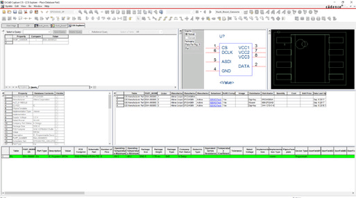
EK Power Solutions conducts a highly detailed validation process for component footprints. OrCAD X Capture CIS provides access to their centralized component database containing every verified part, footprints, symbols, and parametric information. This provides them with the confidence needed to send designs to manufacturing and obtain low failure rates.
Additionally, using OrCAD X Capture CIS allows EK Power Solutions to maintain specific customer PCB files in their own preferred CAD system, as well as providing industry-wide support.
OrCAD X PCB Designer Professional

OrCAD X provides integrated 3D modeling to visualize the final assembly and verify integration with mechanical housing requirements. In addition to realistic modeling, OrCAD X provides collision detection and 3D design rule checks to ensure proper fitment and assembly success. EK Power Solutions leverages these 3D capabilities along with additional advanced features of OrCAD X to create high-quality PCB layouts.
The result was higher-quality PCB designs, reduced manufacturing failure rates, faster development cycles, and stronger customer alignment, positioning EK Power Solutions as an even more attractive and reliable design partner. Read more about how EK Power solutions highly reliable and quality products using OrCAD X here.
Note: EK Power Solutions recently merged with Cumatix to create POWER&D, leveraging 40 years of dedication to power electronics, motion control and development to create unique solutions that match the individual needs of their customers.
