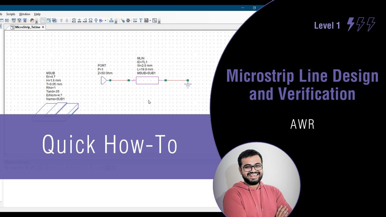
AWR is a comprehensive electronic design automation (EDA) platform for developing RF/microwave products. In this video, we’ll learn how to design a microstrip line in AWR using Tx Line tool and how to verify the transmission line parameters.
Mixed signal circuit design applications span a range of industries due to the ability to efficiently handle analog and digital signals within the same integrated circuit (IC). Achieving the desired IC functionality and performance requires a deep understanding of the characteristics, constraints, and design considerations of analog, digital, and mixed signal circuits. Below, you will find a comparison of the design needs and challenges for these circuit types.
Comparison of Analog, Digital, and Mixed-Signal Circuit Design Requirements
Design Requirement
Analog Circuits
Digital Circuits
Mixed Signal Circuits
Signal Integrity
Critical for maintaining signal fidelity and accuracy
Essential to ensure noise immunity and reliable logic operation
Crucial for accurate analog-to-digital and digital-to-analog conversion
Power Consumption
Emphasis on low power consumption
Power consumption efficiency, especially in high-speed designs
Need for balance between low power consumption and high performance across analog and digital domains
Proper layout and routing techniques to minimize propagation delays and crosstalk
Correct layout to separate analog and digital sections while maintaining signal integrity
Temperature Stability
Stability across temperature ranges important
Less affected by temperature variations
Stability of both analog and digital components across temperature changes needed
Filtering and Signal Conditioning
Filtering and conditioning of signals required
Not applicable
Integration of filtering and conditioning for accurate signal processing required
Logic Design
Not applicable
Logic design essential for implementing functions
Integration of analog and digital logic for mixed-signal processing critical
Testing and Verification
Comprehensive testing to ensure signal fidelity
Testing focused on logic operation and timing
Testing across analog and digital domains to verify performance and accuracy
Mixed Signal Circuit Design
Mixed signal circuit design is pervasive across various industries and applications due to its ability to efficiently handle analog and digital signals within the same integrated circuit. Here are a few examples:
Test and Measurement Equipment: Oscilloscopes, spectrum analyzers, multimeters, and other test and measurement tools require mixed signal circuitry to handle analog and digital signals.
Embedded Systems: It is common for embedded systems, such as microcontrollers and digital signal processors, to incorporate mixed-signal circuitry to communicate with the external world, obtain sensor inputs, and control analog peripherals.
Sensors: Sensors use mixed signal circuits to convert analog outputs into digital signals for processing by microcontrollers or other digital systems. Applications such as industrial automation, automotive systems, and IoT devices commonly use this technology.
Power Management: From mobile phones to industrial power supplies, power management circuits often need mixed signal design for efficient conversion, regulation, and monitoring of power levels.
Communication Systems: In communication systems, such as modems, transceivers, and baseband processing units, mixed signal circuits are used to digitize analog signals, such as audio and video. In addition, these circuits are used in Wi-Fi, Bluetooth, and cellular networks, where analog RF signals need to be processed and modulated/demodulated digitally for transmission and reception.
Consumer Electronics: Mixed signal circuitry is used in many consumer electronics products, including smartphones, tablets, digital cameras, and wearable devices for audio processing, touchscreen interfaces, and power management.
Data Converters: Audio systems, instrumentation, and sensor interfaces rely on mixed signal circuit design for analog-to-digital converters and digital-to-analog converters.
Automotive Electronics: Mixed signal circuits are used in automotive applications such as engine control units, safety systems, infotainment systems, and sensor interfaces for anti-lock braking systems and airbag deployments.
Medical Devices: For patient monitoring, diagnostic imaging, and drug delivery systems, mixed signal circuits process analog sensor inputs digitally for analysis or control.
When it comes to circuit design, it is imperative to have the best design and development software tools and expertise on your side. For mixed signal circuit design applications, effective simulation software capabilities are required for efficient development and to ensure performance objectives will be met. Partnering with an industry leader with experience and expertise in providing engineers with these solutions is the best option.
EMA Design Automationis a leading provider of the resources that engineers rely on to accelerate innovation. We provide solutions that include PCB design and analysis packages, custom integration software, engineering expertise, and a comprehensive academy of learning and training materials, which enable you to create more efficiently. For more information on mixed signal circuit design and how we can help you or your team innovate faster,contact us.
With any design software tool, having an accessible and navigable environment is key for efficient design creation and review. The ideal design environment is completely customized to the designer’s preference. AWR allows you to customize your RF simulation environment to increase productivity with:
A larger work area, giving the designer more space and significantly expedite the design process.
A custom color scheme to create familiarity when transitioning between tools.
Custom keyboard shortcuts essentially automating tedious commands and accelerating the design process.
This quick how-to will provide step-by-step instructions on how to customize your AWR RF simulation environment by expanding the workspace, changing default colors, and adding keyboard shortcuts.
Step 1: Open a blank project in AWR Design Environment.
By default, the AWR workspace has:
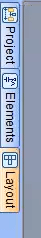
A Project panel on the left with tabs for Elements and Layout at the bottom
A Status Window panel at the bottom showing error and warning messages as well as general information.
The available workspace is shown in gray.
Increasing Workspace Area in AWR
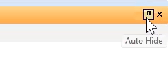
Step 2: Select the Auto Hide button on the Status Window and Project panel toolbars. Tabs to activate the panels are now on the border of the window and the available workspace is much larger.
Note: These settings are retained when AWR Design Environment is closed. Hover your mouse over a tab to open the panel.
Changing Default Colors
Note: By default, all canvases in AWR Design Environment have a white background with a black grid. A separate color scheme can be defined for each type of canvas, such as schematics, system diagrams, and global definitions to improve usability.
Step 3: Select Options > Environment Options from the menu.
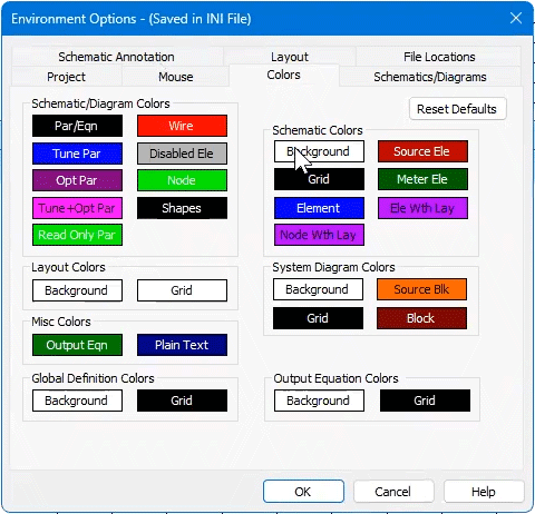
Step 4: The Environment Options window opens. Select Colors.
Color Options in AWR
Step 5: In the Colors tab, select the color for Background to change it.
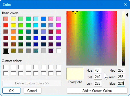
Customizing Colors in AWR
Step 6: Select a color from the Color window and click OK.
Note: Select Define Custom Colors to use a custom color.
Step 7: Back in the Colors tab, select the color for Grid to change it.
Step 8: Select the desired color from the Color window and click OK.
Step 9: Click OK in the Colors tab.
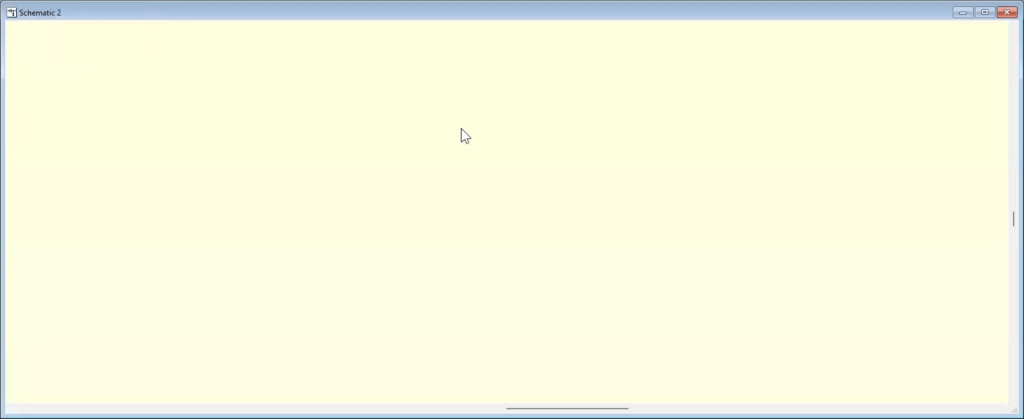
Step 10: View the results. The background and foreground grids have been adjusted to the color(s) you picked.
Note: These color preferences are retained for the next session of AWR Design Environment.
Configuring Keyboard Shortcuts
Note: Keyboard shortcuts can greatly accelerate the design process by reducing mouse-clicks and streamlining commonly used commands.
Step 11: Open a schematic with an S Parameter graph in AWR Design Environment.
Step 12: Select Window > Tile Vertical from the menu to tile the windows within the canvas.
Step 13: Select Simulate from the menu and View the Analyze command on the menu. F8 is the currently defined shortcut key for this command.
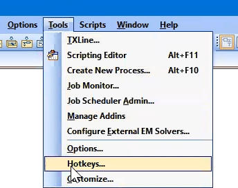
Activating the Customize Window
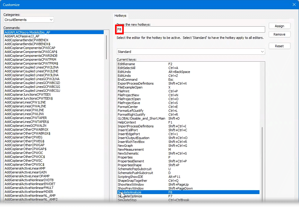
Step 14: Select Tools > Hotkeys from the menu. The Customize window opens, showing the list of available commands and defined hotkeys.
Step 15: View SimulateAnalyze in the Current Keys list. The hotkey is defined as F8 as previously shown in the menu.
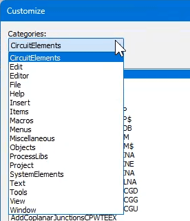
Step 16: Open the Categories drop-down menu for a list of available command categories.
Step 17: Select the desired command from the Command list.
Creating Shortcut Keys in AWR
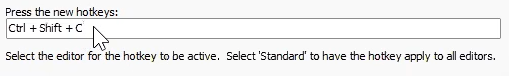
Step 18: Select the Press the New Hotkeys field. Enter the desired keyboard shortcut for the command by pressing the corresponding keys on the keyboard.
Step 19: Click Assign to assign the shortcut. The shortcut can now be used to run the command at any time.
Step 20: Click OK to save the changes and close the window.
Wrap Up & Next Steps
Easily customize your AWR RF Simulation environment and workspace to increase productivity and optimize your design process in AWR. Learn more about AWR and request a free trial here. For more AWR how-tos, visit EMA Academy.
This powerful 3D EM simulator provides RFIC/MMIC, module, and RF PCB designers with high-capacity EM analysis for design verification and signoff of large, complex RF/mixed-signal systems.
Celsius Thermal Solver is integrated within the Cadence AWR Design Environment® platform, providing access to high-capacity electrothermal analysis for design verification and signoff of RF/microwave systems and high-power amplifiers.
AWR is a comprehensive electronic design automation (EDA) platform for developing RF/microwave products. In this video, we’ll learn how to configure and perform Yield Analysis in AWR Microwave Office.
AWR is a comprehensive electronic design automation (EDA) platform for developing RF/microwave products. In this video, we’ll create a diode model from scratch in AWR Microwave Office using a SPICE model and package parasitic provided by manufacturers.
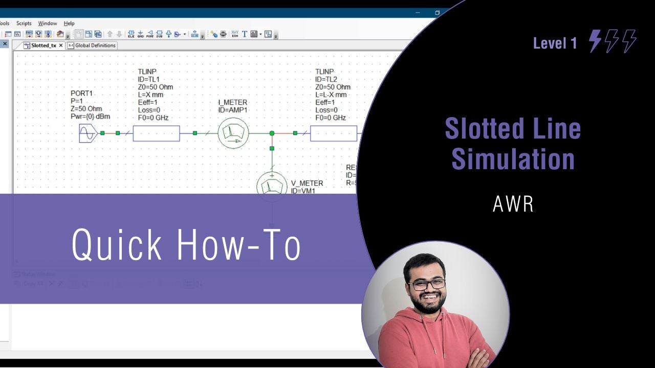
AWR is a comprehensive electronic design automation (EDA) platform for developing RF/microwave products. In this video, we’ll learn to construct a circuit schematic of a slotted transmission line and perform analysis by changing properties using AWR Microwave Office.