Company: OLogic, Inc. Industry: Robotics Solution: Sigrity
OLogic (link is external) is Silicon Valley’s premier consultancy with a focus on robotics and consumer electronics. With a cross-disciplinary team of electrical, software, and mechanical engineers, plus industrial design services, OLogic has domain expertise in every stage of product development from initial concept through working with contract manufacturers to create a product at scale.
When one of Ologic’s electrical engineers, Jeff Comstock, had a client request that required unique mechanical constraints, he knew he had a challenge. The 3D depth camera the client requested would not allow for a regular, right-angle USB-C connector due to the mechanical housing specifications. Generally, this is resolved with cabling, however, this did not meet the client’s needs. Eventually, Ologic concluded that a rigid flex PCB was the appropriate methodology. This introduced new design complexities, validation issues, and USB compliance concerns the team needed to address. As usual, they needed to get this project delivered to the client in a short window and without any issues. Jeff needed a way to virtually prototype and evaluate the design before building to ensure the USB-C interface would be in spec and client delivery timelines could be met.
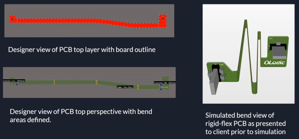
Through Sigrity, Comstock was able to identify that the mesh grid used to create the flexible portion of the design was too big. “We were able to go back to the board house and mention to them that we recommend a smaller one and were able to have an internal conversation and get that before it was already too late on the fab,” Comstock said. This allowed them to reduce tensile stress and avoid cracking within the flexible portion of their design. Sigrity provides Ologic, Inc. with the reliability and accuracy required to consistently complete high-quality designs for their clients.
“What’s important to me is that we’re able to actually add realistic characteristics into this and see how much it deviates from the ideal segment. To go from ideal to the real world and the fact that you can see it change … saves you the time when you actually bring it to the lab and start doing your compliance,” Comstock said.
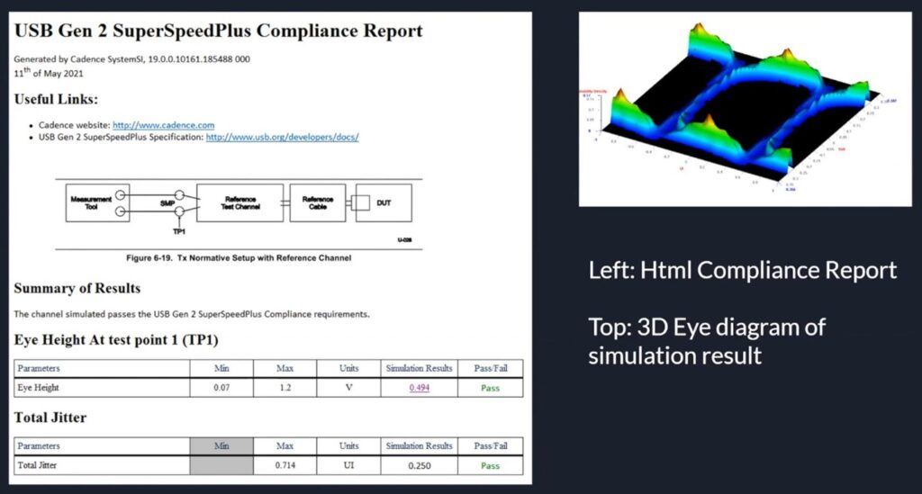
Another component of success for this project was the ease of clear communication. In the past, the process of copy and pasting reports proved cumbersome and error prone. With Sigrity, the team can now easily generate HTML reports which give access to anyone with a browser. “Being able to send my team [the link] and have a quick discussion versus having to go through the process of making a report just saves time and gives better clarity,” said Comstock.
Rather than being set-back with board re-spins or having to correct multiple design issues, Ologic, Inc. and Comstock are confident knowing they are producing high-quality designs the first time around.
By using Sigrity to produce consistent and reliable designs for the real-world, Ologic, Inc. can continue to design with even more confidence. “Where are we building our confidence from? It’s not just the fact that I’m doing it. It’s the fact that I have a report that’s validating my work, and this report is the same outcome I’m going to be looking at when I validate this with my real-world results,” Comstock said.
You can learn more about this project from their CDNLive! Presentation.
Goals
Challenges
Results
” Where are we building our confidence from? … It’s the fact that I have a report that’s validating my work, and this report is the same outcome I’m going to be looking at when I validate this with my real-world results.”
– Jeff Comstock, Electrical Engineer | OLogic, Inc.
