When you create a schematic design, it is critical to accurately convey your PCB design intent by detailing:
- Components
- Net Connections
- Design Functionality
With large designs, manually connecting nets, labeling wires, and creating a schematic can be time consuming. OrCAD X Capture offers a number of time-saving features to keep the design process moving and ensure schematic accuracy, including:
- Object Snapping to Ensure Connections
- Automatic Wire Connections
- Buses for Multiple Connections
- Automatic Bus Entries
- Net Aliases for Distant Connections
This quick how-to will provide step-by-step instructions on how to quickly and efficiently create a schematic with these time-saving features in OrCAD X Capture.
To follow along, download the provided files above the table of contents.
How-To Video
 Open in New Window
Create a Schematic with Object Snapping in OrCAD X Capture
Step 1: Open the provided design in OrCAD X Capture.
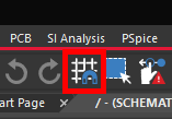
Step 2: Confirm that the Snap to Grid button shows a grid with a magnet, not a singular filled section of grid. This will ensure that all placed objects snap to the grid. It is recommended to leave this feature on at all times during the design process.

Note: If the button shows a singular filled section of grid, grid snap is off. Click the button to re-enable it.
Create a Schematic with Automatic Wiring
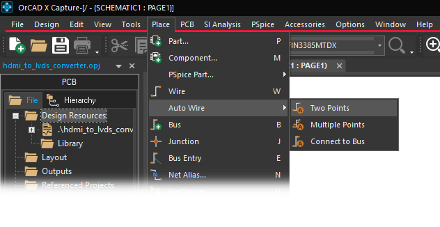
Step 3: Select Place > Auto Wire > Two Points from the menu.
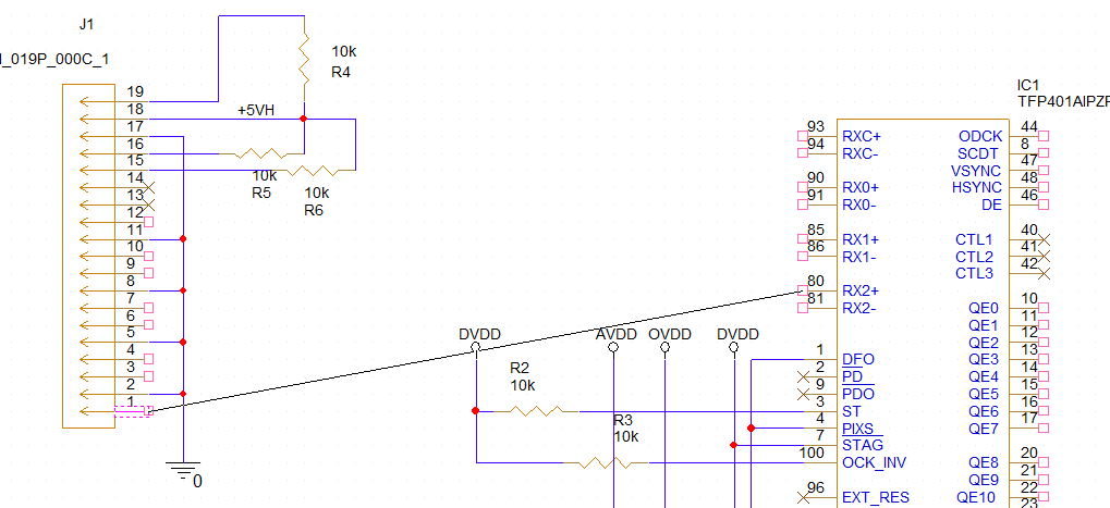
Step 4: Select pin 1 on J1, then pin 80 (RX2+) on IC1. A line extends from the first pin to the cursor.
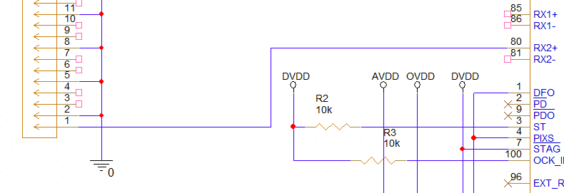
Step 5: Click to automatically draw a wire between the two pins. Right-click and select End Mode when finished.
Step 6: Click and drag the vertical portions of the wire to move them a bit closer to connector J1 to avoid crowding the other input pins for future connections.
Step 7: Select Place > Auto Wire > Two Points from the menu.
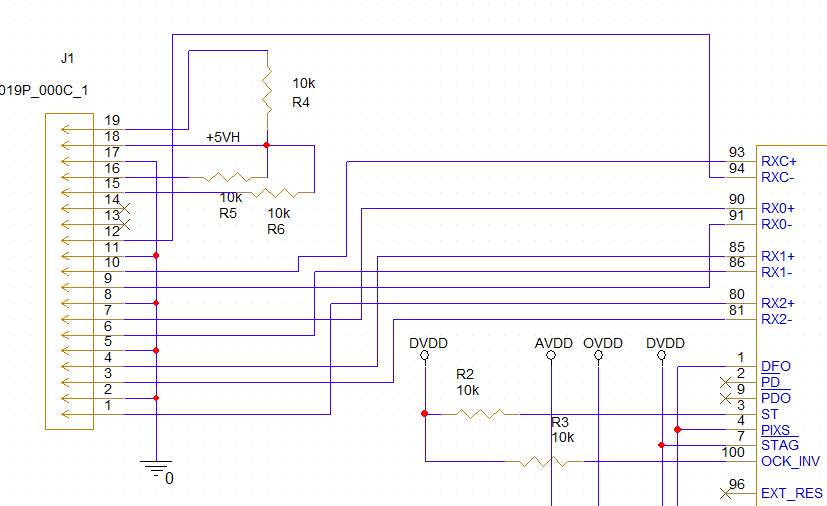
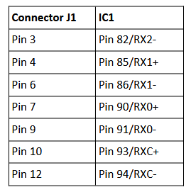
Step 8: Click to create automatic connections between the following pins.
Note: If a connection is not drawn, the software could not find a path between the two points. Exit the automatic wiring mode and adjust the existing connections before trying again. Components can also be wired manually by selecting Place > Wire from the menu.
Creating Buses
Note: This design requires parallel bits to be connected. A bus connection can be used to simplify this.
Step 9: Select Place > Bus from the menu.
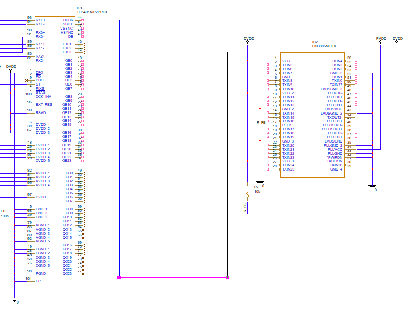
Step 10: Click to route the bus from IC1 to IC2. Right-click and select End Wire when finished.
Step 11: Click to tee the bus and route another section to the other side of IC2. Press Escape on the keyboard when finished.
Placing Bus Entries Automatically
Step 12: Select Place > Auto Wire > Connect to Bus from the menu.
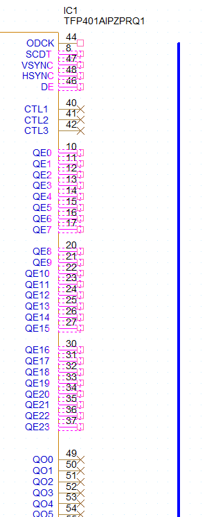
Step 13: Click to select pins 8, 46-48, 10-17, 20-27, and 30-37 on IC1.
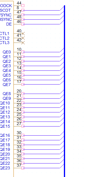
Step 14: Select the bus. The nets are automatically connected to the bus.
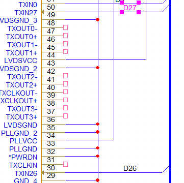
Step 15: The Enter Net Names window opens. Enter D[0:27] for the name and click OK. The connections are automatically numbered D0-D27.
Step 16: Click to select the pins for TXIN5-TXIN25 on IC2.
Step 17: Select the bus to the left of IC2. The nets are automatically connected.
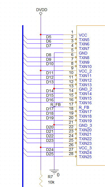
Step 18: In the Enter Net Names window, enter D[5:25] and click OK. The nets have been connected to the bus and named. The nets are numbered from top to bottom.
Step 19: Select the pins for TX0-TX4 on IC2. Select the bus to the right of IC2 to connect the nets.
Step 20: In the Enter Net Names window, enter D[4:0] and click OK.
Note: Since the nets are numbered from top to bottom, starting with a higher number will enumerate the nets from bottom to top.
Placing Bus Entries Manually
Step 21: Select Place > Wire from the menu, the Wire button from the toolbar, or press W on the keyboard.
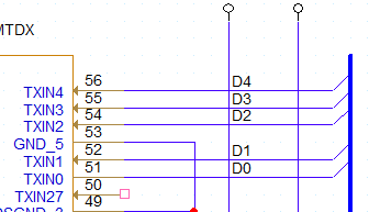
Step 22: Click to draw a wire stub between pin TXIN27 and the bus. Double-click to finish the stub.
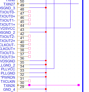
Step 23: Click to draw another stub between TXIN26 and the bus. Double-click to finish the stub, then press Escape on the keyboard.
Step 24: Select Place > Bus Entry from the menu or press E on the keyboard.
Step 25: Click to place entries between each stub and the bus. Use R on the keyboard to rotate if needed.
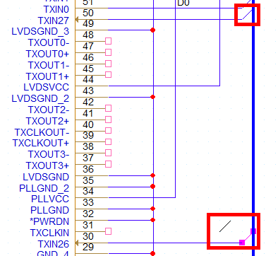
Placing Net Aliases
Note: Net aliases can be placed to electrically connect stubs or nets that cannot be physically connected in the schematic.
Step 26: Select Place > Net Alias from the menu.
Step 27: Enter D26 for the alias and click OK.
Step 28: Click to place an alias on the TXIN26 net, followed by the TXIN27 net. The alias number is incremented automatically.
Wrap Up & Next Steps
Save time and ensure accuracy when you create a schematic with automatic wire connections, net aliases, and more in OrCAD Capture. Test out this feature and more with a free trial of OrCAD. Want to learn more about Capture? Get access to free how-tos, courses, and walk-throughs at EMA Academy.

