In a recent webinar hosted by EMA Design Automation, Ted Larson, CEO and co-founder of engineering services firm OLogic Inc., shared a powerful behind-the-scenes look at how his team turns complex product ideas into functional reality.
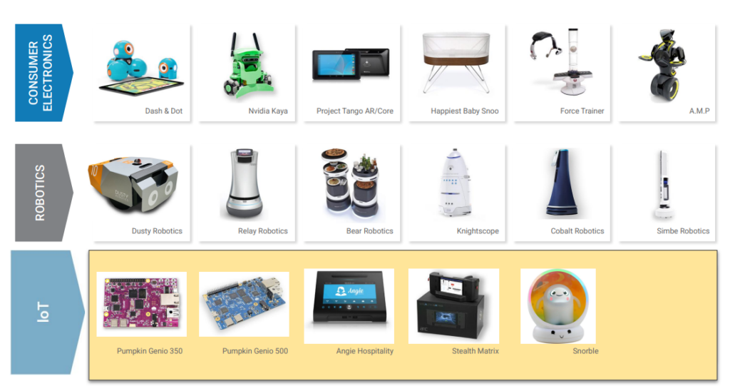
Ted has over 30 years of experience designing and building commercial hardware & software products. His current interests are robotics, artificial intelligence, and embedded systems in consumer and professional electronic devices. Ted graduated from California Polytechnic State University with BS and MS degrees in Computer Science. He has worked on numerous robotics projects with leading corporations including Google, Hasbro, Meta, and Panasonic. Ted is a champion of all things robotics and has given key speeches at several of the past ROBOBusiness Expos and Summits; the Silicon Valley annual conference that has helped business leaders understand where the market is going and to implement their robotics vision in their organizations.
With Ted’s extensive experience, from building dev boards for MediaTek to designing robotics systems, he emphasizes one recurring theme: simulation is essential for design success.
As embedded systems grow more compact and complex, using mobile-grade SoCs, DDR4 memory, and high-speed interfaces, traditional “build and hope” methods are increasingly risky. For OLogic, simulation isn’t just about optimization, it’s the difference between a product that works and one that doesn’t.
The Aha Moment: When Simulation Proved Its Worth
One of the most eye-opening moments came during the development of a USB 3.1 flex cable. OLogic had thoroughly simulated the design using Cadence Sigrity tools and verified that the high-speed signal paths were clean and compliant. But when a manufacturing vendor overseas delivered the first production prototypes the boards didn’t work.
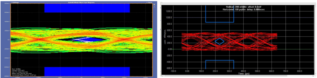
To troubleshoot the design, OLogic made some local prototypes based on the design data sent to the manufacturer and measured simulation results against those boards. This was a breakthrough: the simulation results matched the test boards exactly. This allowed OLogic to determine whether something was different about the boards from the manufacturer- the design had been altered and unauthorized changes were made in the PCB layout.
“The simulation matched the real-world results,” Ted said. “After that, I was like, oh we’re going to simulate everything from here on in because this stuff is really great.”
The simulations turned out to be the key to solving the mystery. By comparing eye diagrams and signal integrity from the failed hardware against the original simulations and test boards, the team was able to find the design had been changed, fix it, and prove to the client that the original design worked based on the test boards and correlated simulations.
Top Reasons to Use Simulation (According to OLogic)
Simulation has become an essential step in the PCB design process to help OLogic develop accurate, high-quality products for their clientele. According to OLogic, the following are the top 5 reasons to incorporate signal integrity and power integrity simulation and analysis with Sigrity:
1. Confidence in First-Pass Success
Simulation enables validation of signal integrity, power integrity, and compliance—before a single board is manufactured.
2. Designing High-Speed Systems on Compact PCBs
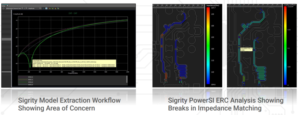
By simulating impedance and return paths, OLogic designed boards with advanced SoCs and split power planes while keeping layer counts down, saving cost and complexity.
3. Catching Costly Vendor Errors
Simulations helped catch critical deviations from spec, like altered trace widths or swapped stackups, that would have been invisible otherwise.
4. Compliance Customization
Sigrity includes built-in tools to verify compliance to industry standards for common devices like DDR4 and PCIe but also allows custom test setups to validate signal performance.
5. Making Design Tradeoffs Visible
From PCB stackup choices to routing methods, simulation made it possible to experiment and iterate with confidence.
According to a recent poll, over 47% of designers are not currently simulating their PCBs to address signal integrity, power integrity, thermal, or EMI/EMC concerns upfront. For these teams, leveraging simulation can be the edge needed to streamline their PCB design process and create high-quality designs the first time.
Tips to Get Started with Simulation: From OLogic’s Playbook
For teams looking to add signal integrity and power integrity simulation to their PCB design workflow, Ted also shared valuable advice:
- Start with what matters: Focus on high-speed or sensitive nets first (USB, PCIe, DDR, HDMI) rather than simulating the whole board.
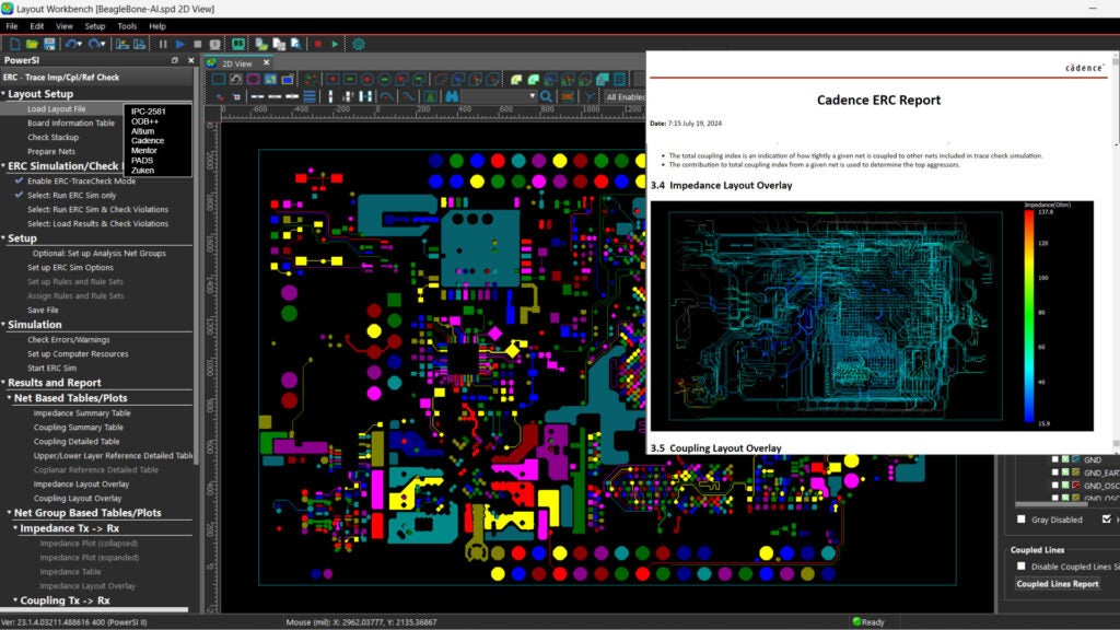
- Find a solution that works with your existing flow if possible: OLogic uses Altium Designer for layout, exporting ODB++ or IPC-2581to Sigrity proving that full toolchain migration isn’t required.
- Validate your PCB stackup early: Work with your fabricator to get accurate material properties (Dk/Df) and enter those into your simulation tools.
- Iterate quickly: Use impedance overlays, eye diagrams, and S-parameters to identify issues, then refine the layout in short loops.
- Don’t wait for failure to simulate: Incorporate simulation as early as possible to catch issues before they’re baked into the board.
Next Steps: Try These Simulation Test Cases to See the Benefits Firsthand
If you’re new to simulation or trying to prove its value within your team, Ted Larson shared two simple, high-impact test cases that can help you get started and see results quickly:
✅ 1. PDN Simulation: Decoupling Matters
Design a power rail with and without decoupling capacitors, then simulate using Cadence Sigrity.
- What you’ll learn: How capacitor quantity, placement, and type affect power integrity.
- Why it’s helpful: This test visually and quantitatively shows how effective decoupling reduces noise and improves stability.
✅ 2. Signal Integrity: Single-Ended Clock with Series Termination
Simulate a single-ended clock signal routed without and then with a series termination resistor, using a post-layout simulation flow.
- What you’ll learn: The impact of reflection, overshoot, and ringing on timing and signal quality.
- Why it’s helpful: It shows how a simple layout and termination decision can make or break signal performance.
“It’s simple to bring a single-ended clock line into Sigrity, sweep the value of the resistor, and see how the shape of the signal changes. You can immediately get rid of the overshoot, undershoot, and everything on the signal-ended clock. This is one of the easiest exercises and very high reward.”
Why Pair Sigrity X with Cadence PCB Tools?
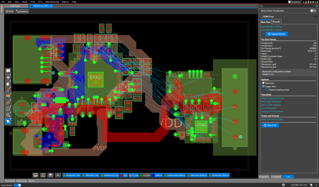
While OLogic integrates Sigrity with Altium using ODB++ or IPC-2581, the tight integration with Cadence’s PCB design tools (like Allegro X and OrCAD X) offers a deeper, more seamless experience:
- Automatic model transfer: Stackups, net classes, and constraints flow directly between layout and simulation.
- Real-time feedback loops: Make changes in layout and revalidate instantly, no exporting or importing needed.
- Automatic accuracy: Shared models and synchronized material data prevent any mismatches between what’s built and what’s analyzed.
- Simplified compliance checking: Built-in validation tools (for USB, PCIe, HDMI, etc.) save time and reduce guesswork.
For teams already on the Cadence platform, Sigrity offers unmatched efficiency and fidelity across the entire simulation workflow.
Final Thoughts
Whether you’re designing smart devices, robotics systems, or custom SoC boards, simulation offers a critical edge, catching problems early, improving reliability, and accelerating time to market. For Ted and the OLogic team, it has become an indispensable part of their process.
As Ted put it, once they saw how simulation could help them accurately model real-world hardware early when the cost of change is lowest, “we’re going to simulate everything from here on in.”
Watch the full webinar, User Stories: Leveraging Cadence Sigrity X from Product Concept to Reality, to learn more about the essential simulations performed by Ted and the OLogic team to increase their design success.