Getting Started with OrCAD X Presto
This lesson will demonstrate how to navigate OrCAD X Presto 23.1 and download the design files, allowing you to follow along with the Presto walk-through series. OrCAD X Presto is a new innovative layout environment focusing on providing a cohesive and comprehensive solution for all PCB design requirements.
 Open in New Window
Downloading the Design Files
Step 1: Select the Materials tab for this lesson.
Step 2: Click to download the [2023]OrCADXPresto_Walkthrough.zip file to your computer.
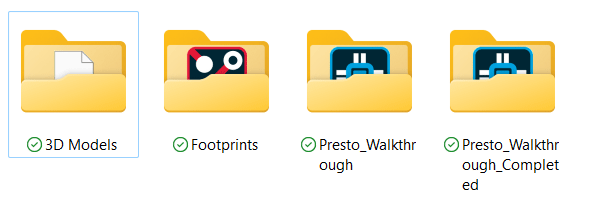
Step 3: Extract the file to your working directory. This directory contains folders containing:
- The referenced Capture design and netlist (\Presto_Walkthrough)
- The completed design (\Presto_Walkthrough_Completed)
- PCB footprints and padstacks (\Footprints)
- 3D STEP models (\3D Models)
Note: Additional files are provided in the Materials tab for each lesson containing a starting design for that lesson.
Step 4: From the provided materials, open the Footprints folder.
Step 5: Press CTRL-A on the keyboard to select all files and press CTRL-C to copy.
Step 6: In another window of File Explorer, navigate to the standard OrCAD PCB Footprint and Padstack library location: C:\Cadence\SPB_23.1\share\pcb\pcb_lib\symbols.
Step 7: Paste the files to this location.
Step 8: From the provided materials, open the 3D Models folder.
Step 9: Press CTRL-A on the keyboard to select all files and press CTRL-C to copy.
Step 10: In the other window of File Explorer, navigate to the standard OrCAD PCB STEP Model library location: C:\Cadence\SPB_23.1\share\local\pcb\step.
Step 11: Paste the files to this location.
OrCAD X Presto Start Page
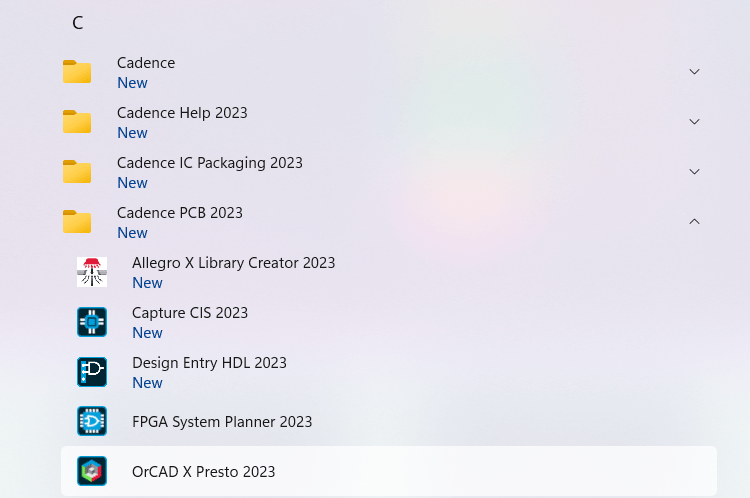
Step 12: Open the Windows Start menu. Expand Cadence 2023 and choose OrCAD X Presto 2023.
Step 13: The Cadence Product Choices window opens. Select the appropriate license and click OK.
Note: Check Use as Default to always run Presto with the selected license.
Step 14: View the OrCAD X Presto start page. The start page contains links to:
- Create a new design
- Open an existing design
- Access manuals and guides
- Utilize design resources
- View Cadence announcements
- Contact local support
- View the latest version of Presto
- Access recently opened designs
The Presto UI
Step 15: Select File > Open from the menu. For this lesson, we will open the design which will be completed throughout this walk-through course to better understand the OrCAD X Presto design environment and scope of the course.
Step 16: Select the completed presto_tutorial.brd file and click Open.
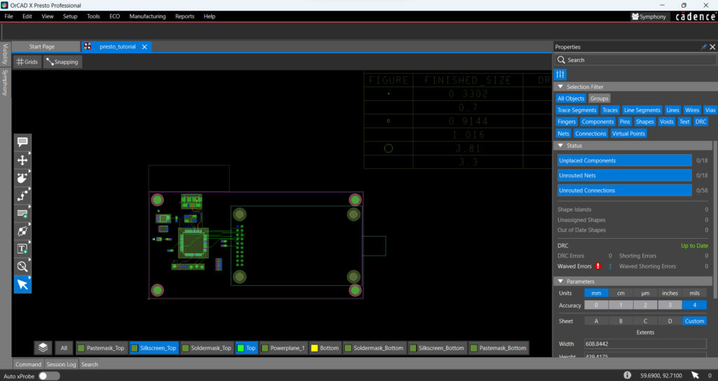
Step 17: View the OrCAD X Presto design environment.
The OrCAD X Presto design environment has been optimized and designed to improve productivity and efficiency throughout the PCB design process. The PCB canvas is in the middle of the screen with easy access to commands and settings with panels and menus around the canvas. All panels can be docked or floating.
The Visibility Panel
Step 18: Select the Visibility button on the left side of the window to open the Visibility panel.
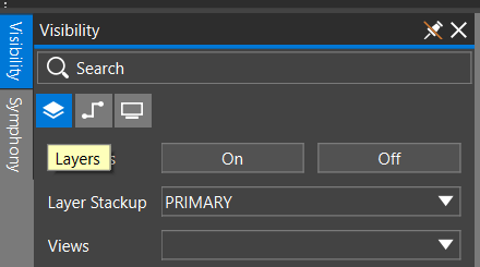
Step 19: Select the Layers button in the Visibility panel.
Here you can view and configure visibility and color for all layers in the board design. You also have options to view varying stack-up configurations in the design as well as pre-configured views.
Step 20: Select All Layers ON.
Step 21: Click to select or deselect commonly viewed aspects of the PCB design in the Objects and Areas section of the Visibility panel. This will display or hide a category from the PCB canvas.
Step 22: Scroll down to the color selection subpanel. Left click a color to turn the selection on or off. Right-click a selection to change the color.
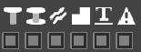
Note: Visibility and colors can be set for the following categories, each indicated by an icon. Icons represent the categories listed below from left to right.
- Pins
- Vias
- Traces
- Shapes
- Text
- DRC
Step 23: Scroll down to the visibility categories. This provides easy visibility access to items commonly viewed on the PCB including:
- Geometries
- Components
- Manufacturing
- Rigid-Flex
- Surface Finishes
- Data Layers
Step 24: Select the eye to turn off all layers defined in a category.
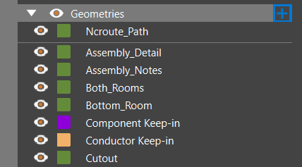
Step 25: Click the arrow to expand a category.
Step 26: Select the ‘+’ to add a layer into the category.
The layer will be named [category]_1 by default. To change the name, double-click and enter the new name. Press Enter on the keyboard to finish. Adjust the color as desired by right-clicking on the assigned color. To delete, right-click the layer and select Delete.
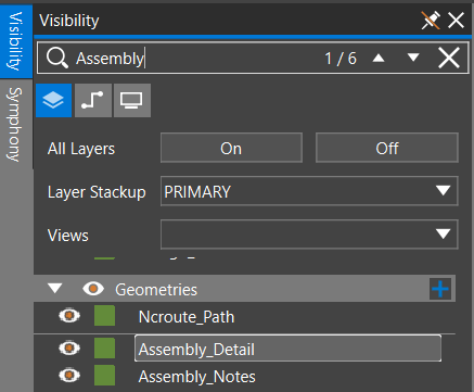
Step 27: In the Search bar, enter a layer name, such as Assembly.
This will list all layers that contain that name. Use this to efficiently locate and adjust visibility for specific layers in the design. Use the arrows to navigate between occurrences. The search bar can be used in any of the visibility panels: layers, nets, or display.
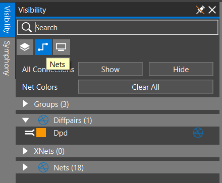
Step 28: Select the Nets button in the Visibility panel to view the net options.
Here you can set colors and toggle visibility for individual nets and net groups. Efficient access has been provided for ratsnest visibility and net color reset.
Step 29: Click to expand a category. Categories are included for easy access to:
- Groups
- Differential Pairs
- XNets
- Nets
Step 30: Double-click the net image to highlight the net in the canvas. Select the color box for the net to change its color.
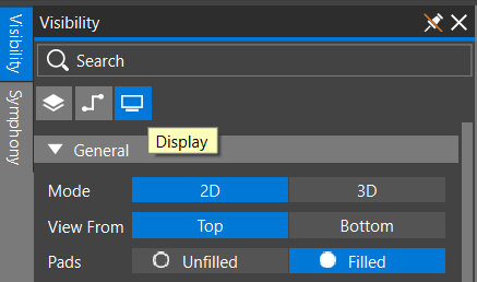
Step 31: Select the Display button in the Visibility panel to view the display options.
Step 32: Select the 3D mode. This provides access to the integrated and improved 3D Canvas.
Step 33: Select the 2D mode to return to the 2D PCB canvas.
Step 34: Select the Top and Bottom modes to view the top and bottom sides of the board, respectively.
Step 35: Click the toggles to turn on or off the net labels and other labels in the design.
Step 36: Left click the colors to change them for common display features such as alignment lines and drills. Click the color to define the desired selection.
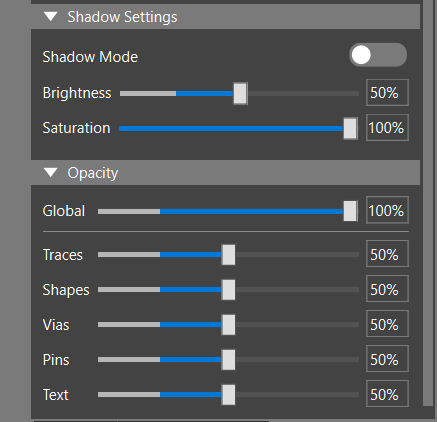
Step 37: Scroll down in the Display Visibility panel. Here you can configure shadows and opacity of the design and specific elements.
Step 38: Select the Visibility button again to close the panel.
Note: Do not click the X in the panel headerbar to close the panel. This will remove the button from the side of the window. The pin at the top of the headerbar is configured to automatically hide the visibility panel. Select the pin icon again to have the visibility panel undocked and visible.
Floating Layer Toolbar
The Floating Layer Toolbar is present at the bottom of the window providing easy access to layer and view visibility. The Floating Toolbar can be used to quickly set visibility for common layers without opening the Visibility panel.
Step 39: Click and drag the floating layer toolbar to move it to the desired location. If placed on the side of the canvas, the options will be arranged vertically.
Step 40: Click to select a layer to turn its visibility on or off.
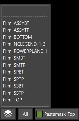
Step 41: Right-click the Films button and select an artwork film from the pop-up menu. The visibility changes to only show layers in that film.
Step 42: Select All to turn on or off visibility for all layers.
Grids and Snapping
Step 43: Select the Grids button to open the Grids widget.
Here you can easily adjust Grid settings with pre-configured grid spacing options in mils, mm, and microns or define the desired grid spacing.
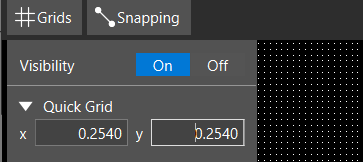
Step 44: Select On for Visibility to turn the grid on.
Step 45: Enter 0.254 in the Quick Grid fields for x. This will change the grid spacing to 0.254mm, or 10 mils, for both dimensions.
Step 46: Select the Snapping button to open the Snapping widget.
Here you can configure how the various objects on your board snap for accurate placement and layout. Easily select On or Off at the top of the widget to turn snapping on or off respectively.
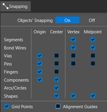
Step 47: Uncheck Alignment Guides to turn the alignment guides off. Alignment Guides can be used to efficiently align components and objects during placement in the PCB canvas.
Step 48: Click Snapping again to close the widget or click anywhere outside the widget to close it.
The Properties Panel
A properties panel is open on the right side of the window, showing the editable properties for the design or a selected component.
Note: If the Properties panel is not visible on the right side of the window, select View > Panels > Properties from the menu. If no component is selected, this panel shows general design properties.
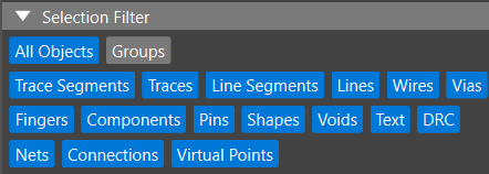
Step 49: View the Selection Filter. This provides easy access to common design elements. Click to select or deselect an object. When working in the PCB canvas only the configured objects will be selected.
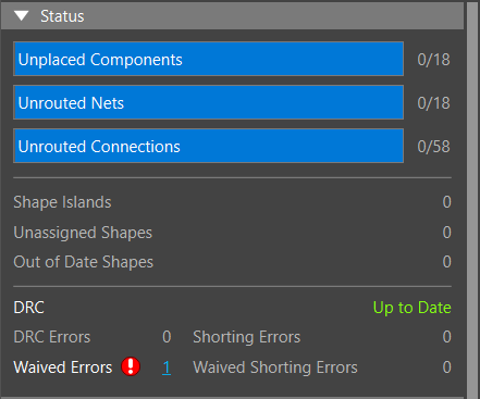
Step 50: View the Design Status. This provides vital information upfront including unplaced components, unrouted nets, design rule errors, and more.
Step 51: Under Parameters, select sheet A2 to change the extents to the A2 metric size.
Note: If an imperial unit is selected for the unit, the available sheet sizes will change to the Imperial A-D. If a metric unit is selected, the available sheet sizes shown are the metric A1-A4. Here you can also configure the accuracy of the design and manually set extents of the PCB canvas. Changing units may introduce DRC errors, if the existing numbers in the design are not rounded off properly.
Step 52: In the Selection Filter subpanel, select All Objects to turn off all objects. Select Components to only allow components to be selected on the board.
Step 53: In the PCB canvas, click and drag to select the entire board. Only the components are selected.
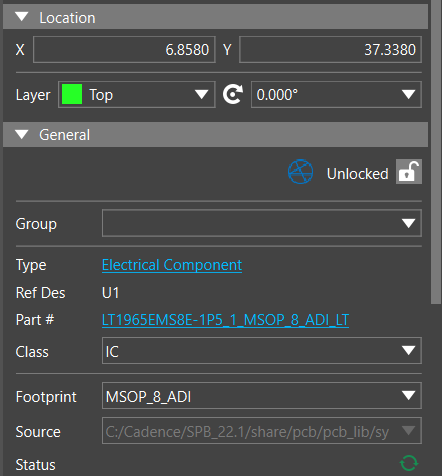
Step 54: Click to select a component on the PCB. View the Properties panel. The following properties are listed for the component:
- Location: The X and Y coordinates of the component.
- Rotation: The rotation of the component.
- Layer: The layer the component is placed on.
- Group: The group the component belongs to (if defined)
- Reference Designator: The reference designator of the component.
- Part Number: The part number.
- Footprint: The PCB footprint.
Step 55: Click anywhere on the canvas to deselect the component.
The Toolbar
The Toolbar provides centralized and easy access to the commands and actions required to create your PCB layout.
Note: This can be moved anywhere within the PCB canvas based on your design preferences. Click and drag to move the toolbar.
Step 56: View the toolbar located on the left of the PCB canvas.
Step 57: Hover over an icon to view more information.
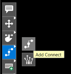
Step 58: If the icon includes an arrow on the top right corner, right-click to expand the category and view additional commands.
Step 59: Click a command to activate it and press Escape on the keyboard to end the command.
The Main Menu
This main menu provides additional access for common design tasks.
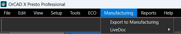
Step 60: View and explore the menu at the top of the screen. The following menu items are available.
- File: Save, load, or import a board file.
- Edit: Cut, copy, and paste design elements.
- View: Change the board view or panel visibility.
- Setup: Configure common design parameters.
- Tools: Configure constraints, the board stackup, and mechanical symbols.
- ECO: Update the schematic and PCB or place all components at once with Quickplace.
- Manufacturing: Export manufacturing documentation.
- Reports: Export design reports.
- Help: View help documentation.
The Search Panel
The Search panel shows all objects in the design and can be filtered to efficiently find components, shapes, design rule check (DRC) errors and more.
Step 61: Select View > Panels > Search from the menu to activate the Search panel at the bottom of the screen.
Step 62: Click and drag to move the panel and dock it on the bottom of the screen. Select Search to close the panel.
Setting Shortcuts and Commands
For an easier design experience, custom shortcut and command keys can be easily configured in OrCAD X Presto.
Step 63: Select Edit > Preferences from the menu.
Step 64: Select Shortcuts (Hotkeys) from the option list.
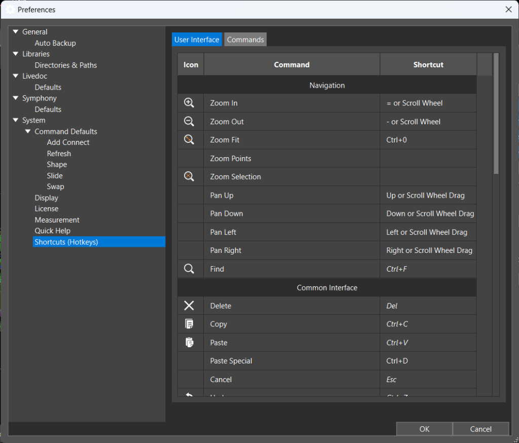
Step 65: View the shortcut list under the User Interface tab. To change a shortcut, double-click the cell under Shortcut and enter the desired keystroke.
Note: Some commands and shortcuts are displayed in italics indicating the command cannot be changed.
Step 66: Select the Commands tab. View the available commands.
Configuring Quick Help
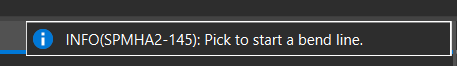
Quick Help opens a tooltip when designing in the PCB canvas to provide additional information or instructions on how to perform a selected command in the PCB canvas.
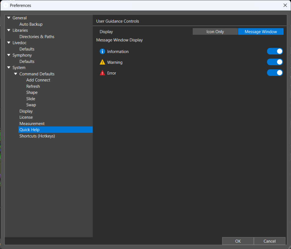
Step 67: Still in the Preferences window, select Quick Help from the options list. Here you can configure which messages to display and whether to display just the icon or a full message window.
Step 68: Click OK to save any settings and close the Preferences window.
Viewing Help Documentation
OrCAD X Presto includes documentation and tutorials to help get you started quickly.
Step 69: Select Help > Documentation from the menu.
Step 70: A new Doc Assistant window opens with the table of contents for the Presto User Guide visible. Scroll through the file to view the available information and tutorials.
Step 71: Close the Doc Assistant window.
Step 72: Back in Presto, click the X on the tab for the board design to close the PCB.